
Data Merger
Efficiently concentrates multiple data sources into a single output using a tree-based buffered pipeline. Provides distributed buffering to handle data collisions without packet loss.
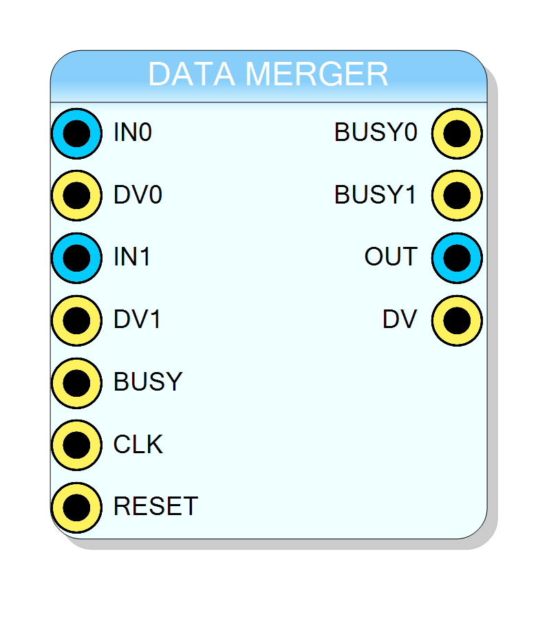
Introduction
The Data Merger block efficiently concentrates multiple data sources into a single output stream using a tree-based buffered pipeline. Unlike the Round Robin Arbiter which uses central scheduling, the Data Merger distributes buffering throughout a binary tree structure, allowing it to handle simultaneous data arrivals without packet loss.
This block is ideal when:
- Multiple asynchronous sources need to be merged
- Data arrives unpredictably from multiple channels
- You need efficient resource utilization with distributed buffering
- Temporal ordering across channels is not required
Pin Description
Backpressure output for channel x.
- HIGH (1): Input buffer full, stop sending data
- LOW (0): Ready to accept data Connect to flow control of upstream data source.
Properties
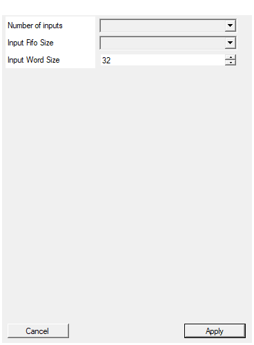
Set the number of input to the virtual block
Number of input channels. Determines tree structure depth. Available values: 2, 4, 8, 16, 32, default 2.Default: 2
Options: 2 4 8 16 32
Set the size of the input buffer in front of each input
Default: 64
Options: 0 64 128 512 1024
Set the input word size in bits
Width of each data word in bits. Range: 2 to 1024, default 32.Default: 32
Range: 2 – 1024
Usage
Data Merger vs Round Robin Arbiter
| Feature | Data Merger | Round Robin Arbiter |
|---|---|---|
| Architecture | Binary tree with distributed buffers | Central arbiter with timeslots |
| Scheduling | Collision-based, first-come priority | Time-division with configurable slots |
| Buffering | Distributed at each tree node | Centralized (external or FIFO version) |
| Priority | Lower channel ID wins collisions | Round-robin fair scheduling |
| Temporal order | Not guaranteed across channels | Preserved within timeslots |
| Latency | Variable (depends on tree depth) | Predictable |
| Best for | Asynchronous, bursty data | Continuous, balanced streams |
When to use Data Merger:
- Data arrives sporadically from many channels
- You don’t need strict temporal ordering
- Resources should be distributed, not centralized
When to use Round Robin Arbiter:
- Continuous data streams from all channels
- Need fair, time-based scheduling
- Temporal ordering matters
Tree Architecture
The Data Merger uses a binary tree structure where each node is a 2-way merger:
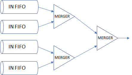
32-Input Tree Structure:
Level 0 (Inputs): [0][1] [2][3] [4][5] [6][7] ... [28][29] [30][31]
↓ ↓ ↓ ↓ ↓ ↓
Level 1 (16 mergers): [M] [M] [M] [M] ... [M] [M]
↓ ↓ ↓ ↓ ↓ ↓
Level 2 (8 mergers): [===M===] [===M===] ... [===M===]
↓ ↓ ↓
Level 3 (4 mergers): [====M====] ... [====M====]
↓ ↓
Level 4 (2 mergers): [========M========]
↓
Level 5 (Output): OUTPUT
Available configurations: 2, 4, 8, 16, or 32 inputs
Distributed Buffering Concept
Each 2-way merger node contains hold registers that buffer data when collisions occur:
Basic Merger Node:
Input A ──────►┌──────────────┐
DV_A ─────────►│ │
│ MERGER │────► Output
Input B ──────►│ │
DV_B ─────────►│ [Hold_A] │────► DV_Out
│ [Hold_B] │
Busy_Out ◄─────│ │◄──── Busy_In
└──────────────┘
▲ ▲
Busy_A Busy_B
Collision handling:
- If only A has data → transmit A
- If only B has data → transmit B
- If both A and B have data → transmit A, buffer B in hold register
- If hold register has data → transmit from hold before accepting new data
This distributed approach means:
- No single point of congestion
- Buffers are spread throughout the tree
- Each node handles its own collisions locally
Serialization of Simultaneous Data
When multiple inputs have data simultaneously, the tree serializes them:
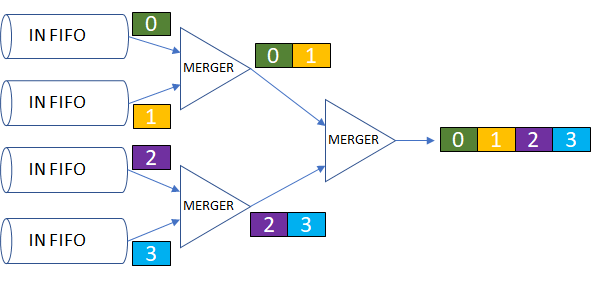
Priority rule: At each merger node, the input with lower channel ID (input A) has priority.
Temporal Order Warning
Important: The Data Merger does NOT guarantee temporal order across channels.
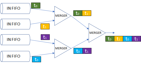
Data from different channels follows different paths through the tree, so arrival order at the output may differ from the original input order:
Example: Data sent at same time from CH0 and CH7
CH0 path: IN_0 → M(0,1) → M(0-3) → M(0-7) → OUTPUT
CH7 path: IN_7 → M(6,7) → M(4-7) → M(0-7) → OUTPUT
Both paths have different delays due to tree traversal!
If temporal ordering matters, consider:
- Adding timestamps to your data
- Using the Round Robin Arbiter instead
- Post-processing to sort by timestamp
Input FIFO Buffering
Each input channel can have an optional input FIFO (configurable via Input Fifo Size property):
| FIFO Size | Use Case |
|---|---|
| 0 | No input FIFO (direct connection) |
| 64 | Light buffering for low-rate sources |
| 128 | Moderate buffering |
| 512 | High-rate sources |
| 1024 | Bursty data with backpressure |
When the input FIFO (or internal hold register) becomes full, the BUSY output goes HIGH, signaling the source to stop sending.
Backpressure Propagation
Backpressure flows backwards through the tree:
When the downstream module asserts BUSY:
- Output stops immediately
- Internal tree buffers start filling
- When buffers approach capacity, BUSY propagates to inputs
- Sources must stop sending when their BUSY goes HIGH
Practical Example: Multi-Channel Detector Readout
Scenario: 8 detector channels, each producing event data packets
Detector 0 ─► Packet Builder ─► IN_0
Detector 1 ─► Packet Builder ─► IN_1
Detector 2 ─► Packet Builder ─► IN_2
Detector 3 ─► Packet Builder ─► IN_3 OUT ─► USB/Ethernet
Detector 4 ─► Packet Builder ─► IN_4 DV ─► Endpoint
Detector 5 ─► Packet Builder ─► IN_5
Detector 6 ─► Packet Builder ─► IN_6 BUSY_x ◄─ (flow control)
Detector 7 ─► Packet Builder ─► IN_7
BUSY ◄─ Endpoint Full
Configuration:
- Number of inputs: 8
- Input Word Size: 32 (typical packet word)
- Input FIFO Size: 512 (handles burst events)
Why Data Merger works here:
- Events are asynchronous (physics triggers)
- Each detector produces independent data packets
- Packets include channel ID, so temporal order can be reconstructed
- Tree structure efficiently handles collision bursts
Application Example: Multi-ADC Data Acquisition
Scenario: 4 ADCs sampling at different rates, need to merge into single stream
ADC_0 (1 MHz) ──► Frame Packer ──► IN_0 Data Format:
ADC_1 (500 kHz) ► Frame Packer ──► IN_1 [Header: CH_ID + Timestamp]
ADC_2 (1 MHz) ──► Frame Packer ──► IN_2 [Sample 0]
ADC_3 (2 MHz) ──► Frame Packer ──► IN_3 [Sample 1]
...
OUT ──► FIFO ──► Readout
Key considerations:
- Each ADC frame includes channel ID and timestamp
- Higher-rate ADCs (CH3) may dominate output temporarily
- Input FIFOs absorb rate mismatches
- Software reconstructs temporal order using timestamps
Timing and Latency
| Parameter | Value |
|---|---|
| Minimum latency | 2 clock cycles (2-input) |
| Typical latency | 2-10 cycles (depends on tree depth) |
| Worst-case latency | Variable (depends on collisions) |
| Throughput | Up to 1 word/clock when no collisions |
Tree depth and latency:
| Inputs | Tree Levels | Min Latency |
|---|---|---|
| 2 | 1 | 2 cycles |
| 4 | 2 | 4 cycles |
| 8 | 3 | 6 cycles |
| 16 | 4 | 8 cycles |
| 32 | 5 | 10 cycles |
Resources & Timing
-
Latency: 2 to 10 clock cycles (depends on tree depth)
-
Throughput: Up to 1 word per clock cycle (collision-dependent)
Uses binary tree of 2-way mergers. Optional input FIFOs use xpm_fifo_async (Xilinx) or dcfifo (Intel). Resource usage scales with input count and FIFO size.