
FX OFFSET TM
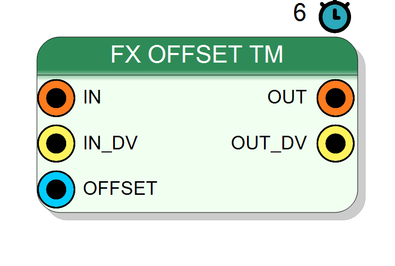
Time-multiplexed fixed-point adder/offset block implemented using Xilinx HLS. Adds a configurable fixed-point offset to TM data streams. Supports signed/unsigned arithmetic with independent bit width configuration for input, offset, and output (integer + fractional parts). Pipeline latency: 6 cycles.
Introduction
This block adds a fixed-point offset value to each sample of a time-multiplexed (TM) input stream, producing a baseline-corrected output stream.
On every rising edge of CLK, if IN_DV = 1, the component performs:
$$ \mathrm{OUT}(n) = \mathrm{IN}(n) + \mathrm{OFFSET}, $$
where all operands are fixed-point numbers with configurable integer and fractional bit widths. The TM Factor property determines how many parallel samples are processed per clock cycle.
Pin Description
(IN Integer + IN Fraction) × TM Factor
Each TM phase receives its corresponding slice of the input bus.
OFFSET Integer + OFFSET Fraction
Applied to all TM phases. Can be connected to a register or constant.
Default sign: SIGNED (allows negative offsets for baseline subtraction).
(OUT Integer + OUT Fraction) × TM Factor
Valid data appear after 6 clock cycles from input.
Properties
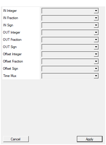
Number of bits of the integer part of the input
Number of integer bits of the input signal ($I_\text{in}$). Range: 0 – 128. Together with IN Fraction, defines the input dynamic range and precision.Default: 16
Options: 0 1 2 3 4 5 6 7 8 9 10 11 12 13 14 15 16 17 18 19 20 21 22 23 24 25 26 27 28 29 30 31 32 33 34 35 36 37 38 39 40 41 42 43 44 45 46 47 48 49 50 51 52 53 54 55 56 57 58 59 60 61 62 63 64 65 66 67 68 69 70 71 72 73 74 75 76 77 78 79 80 81 82 83 84 85 86 87 88 89 90 91 92 93 94 95 96 97 98 99 100 101 102 103 104 105 106 107 108 109 110 111 112 113 114 115 116 117 118 119 120 121 122 123 124 125 126 127 128
Number of bits of the fractional part of the input
Number of fractional bits of the input signal ($F_\text{in}$). Range: 0 – 128. Higher values provide better precision but increase bit width.Default: 0
Options: 0 1 2 3 4 5 6 7 8 9 10 11 12 13 14 15 16 17 18 19 20 21 22 23 24 25 26 27 28 29 30 31 32 33 34 35 36 37 38 39 40 41 42 43 44 45 46 47 48 49 50 51 52 53 54 55 56 57 58 59 60 61 62 63 64 65 66 67 68 69 70 71 72 73 74 75 76 77 78 79 80 81 82 83 84 85 86 87 88 89 90 91 92 93 94 95 96 97 98 99 100 101 102 103 104 105 106 107 108 109 110 111 112 113 114 115 116 117 118 119 120 121 122 123 124 125 126 127 128
Select if the input is signed or unsigned. Sign uses 1 bit of the integer part
Arithmetic type of the input signal:
UNSIGNED→ Non-negative values only, range [0, 2^N - 1]SIGNED→ Two’s complement, range [-2^(N-1), 2^(N-1) - 1]
The sign bit uses 1 bit of the integer part.
Default: UNSIGNED
Options: UNSIGNED SIGNED
Number of bits of the integer part of the output
Number of integer bits of the output signal ($I_\text{out}$). Range: 0 – 128. Should be sized to prevent overflow: typically ≥ max(IN Integer, OFFSET Integer) + 1.Default: 16
Options: 0 1 2 3 4 5 6 7 8 9 10 11 12 13 14 15 16 17 18 19 20 21 22 23 24 25 26 27 28 29 30 31 32 33 34 35 36 37 38 39 40 41 42 43 44 45 46 47 48 49 50 51 52 53 54 55 56 57 58 59 60 61 62 63 64 65 66 67 68 69 70 71 72 73 74 75 76 77 78 79 80 81 82 83 84 85 86 87 88 89 90 91 92 93 94 95 96 97 98 99 100 101 102 103 104 105 106 107 108 109 110 111 112 113 114 115 116 117 118 119 120 121 122 123 124 125 126 127 128
Number of bits of the fractional part of the output
Number of fractional bits of the output signal ($F_\text{out}$). Range: 0 – 128. Typically set to max(IN Fraction, OFFSET Fraction) for full precision.Default: 0
Options: 0 1 2 3 4 5 6 7 8 9 10 11 12 13 14 15 16 17 18 19 20 21 22 23 24 25 26 27 28 29 30 31 32 33 34 35 36 37 38 39 40 41 42 43 44 45 46 47 48 49 50 51 52 53 54 55 56 57 58 59 60 61 62 63 64 65 66 67 68 69 70 71 72 73 74 75 76 77 78 79 80 81 82 83 84 85 86 87 88 89 90 91 92 93 94 95 96 97 98 99 100 101 102 103 104 105 106 107 108 109 110 111 112 113 114 115 116 117 118 119 120 121 122 123 124 125 126 127 128
Select if the output is signed or unsigned. Sign uses 1 bit of the integer part
Arithmetic type of the output signal:
UNSIGNED→ Unsigned result (if inputs are both unsigned and non-negative)SIGNED→ Signed result (required if input or offset are signed)
Default: UNSIGNED
Options: UNSIGNED SIGNED
Number of bits of the integer part of the offset
Number of integer bits of the offset value ($I_\text{offset}$). Range: 0 – 128. Should accommodate the maximum offset magnitude required.Default: 16
Options: 0 1 2 3 4 5 6 7 8 9 10 11 12 13 14 15 16 17 18 19 20 21 22 23 24 25 26 27 28 29 30 31 32 33 34 35 36 37 38 39 40 41 42 43 44 45 46 47 48 49 50 51 52 53 54 55 56 57 58 59 60 61 62 63 64 65 66 67 68 69 70 71 72 73 74 75 76 77 78 79 80 81 82 83 84 85 86 87 88 89 90 91 92 93 94 95 96 97 98 99 100 101 102 103 104 105 106 107 108 109 110 111 112 113 114 115 116 117 118 119 120 121 122 123 124 125 126 127 128
Number of bits of the fractional part of the offset
Number of fractional bits of the offset value ($F_\text{offset}$). Range: 0 – 128. Match this to input fractional bits for seamless addition.Default: 0
Options: 0 1 2 3 4 5 6 7 8 9 10 11 12 13 14 15 16 17 18 19 20 21 22 23 24 25 26 27 28 29 30 31 32 33 34 35 36 37 38 39 40 41 42 43 44 45 46 47 48 49 50 51 52 53 54 55 56 57 58 59 60 61 62 63 64 65 66 67 68 69 70 71 72 73 74 75 76 77 78 79 80 81 82 83 84 85 86 87 88 89 90 91 92 93 94 95 96 97 98 99 100 101 102 103 104 105 106 107 108 109 110 111 112 113 114 115 116 117 118 119 120 121 122 123 124 125 126 127 128
Select if the offset is signed or unsigned. Sign uses 1 bit of the integer part
Arithmetic type of the offset value:
UNSIGNED→ Positive-only offset (adds baseline)SIGNED→ Allows negative offsets (baseline subtraction)
Default: SIGNED (most common for pedestal/baseline correction).
Default: SIGNED
Options: UNSIGNED SIGNED
Set number of samples for each clock cycle
Number of time-multiplexed phases (parallel samples per clock). Allowed values: 2, 4, 8, 16, 32. Higher values increase throughput proportionally but consume more FPGA resources (one HLS instance per TM factor).Default: 4
Options: 2 4 8 16 32
Functional description
The component implements fixed-point addition using Xilinx HLS (High-Level Synthesis) and replicates the operation N times (where N = TM Factor) to support time-multiplexed data streams with high throughput.
Fixed-point format
Each signal (IN, OFFSET, OUT) is configured with:
- Integer bits: Number of bits for the integer part
- Fractional bits: Number of bits for the fractional part
- Sign: SIGNED or UNSIGNED arithmetic
Total bit width = Integer bits + Fractional bits.
Input modes
- IN: TM bus of width
(IN Integer + IN Fraction) × TM Factor - OFFSET: Scalar fixed-point value of width
OFFSET Integer + OFFSET Fraction - OUT: TM bus of width
(OUT Integer + OUT Fraction) × TM Factor
The OFFSET input is not time-multiplexed and applies to all TM phases.
Data valid handshake
IN_DV(input): Input data valid signal, active highOUT_DV(output): Output data valid signal, active high (after 6 cycle latency)
Mathematical background
For fixed-point addition with different scales:
- Input $x$ with $I_x$ integer bits and $F_x$ fractional bits
- Offset $o$ with $I_o$ integer bits and $F_o$ fractional bits
The mathematical sum requires alignment:
$$ y = x + o = x \cdot 2^{-F_x} + o \cdot 2^{-F_o} $$
When $F_x = F_o$, addition is straightforward. When fractional widths differ, the HLS core handles automatic alignment and scaling.
Typical output sizing to prevent overflow:
- OUT Integer ≥ max(IN Integer, OFFSET Integer) + 1
- OUT Fraction = max(IN Fraction, OFFSET Fraction)
Timing
The HLS-generated IP has a fixed pipeline latency of 6 clock cycles:
| Property | Latency (clock cycles) |
|---|---|
| FX OFFSET TM | 6 |
Total system delay: T_delay = 6 × T_CLK.
In TM mode, all phases operate in parallel with the same latency.
Typical use cases
- Baseline restoration in ADC data acquisition
- DC offset compensation in detector readout chains
- Pedestal subtraction in nuclear/particle physics experiments
- Signal centering before filtering or threshold discrimination
Waveform example
Example with TM Factor = 4, Input = [100, 150, 200, 250], OFFSET = -100 (signed).
Note: 6 clock cycles of latency from input to output.