
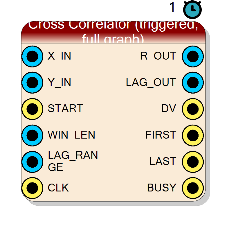
Cross Correlator (triggered, full graph)
On a rising edge of START, captures WIN_LEN consecutive X and Y samples into internal BRAM, then sweeps the lag from -LAG_RANGE to +LAG_RANGE and streams out the whole R[k] correlogram on R_OUT / LAG_OUT / DV. The inner MAC loop is II=1 so total time is approximately WIN_LEN * (2*LAG_RANGE + 1) clocks.
Introduction
For every requested lag $k$, the block computes
$$ R[k] = \sum_{\substack{0 \le n < \text{WIN_LEN} \ 0 \le n-k < \text{WIN_LEN}}} X[n] \cdot Y[n-k] $$
and outputs it as a stream of $2 \cdot \text{LAG_RANGE} + 1$ bins, in order $k = -\text{LAG_RANGE}, \ldots, 0, \ldots, +\text{LAG_RANGE}$.
Unlike the real-time single-lag block, this component is not throughput- bound: after a trigger it “takes as long as it needs” (typically a few million clocks for a 1k-sample window with 128 lags) but only requires a handful of MAC resources (one product per clock, II=1).
Pin Description
Properties
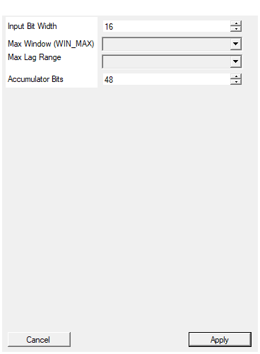
Bit width of the signed X and Y input samples
Bit width of X and Y (signed). 4..32 bits.Default: 16
Range: 4 – 32
Maximum runtime value of WIN_LEN. Sizes the two X/Y capture BRAMs (each holds WindowMax samples of InputSize bits).
Maximum runtime value of WIN_LEN. Sizes the X and Y capture BRAMs (eachWindowMax * InputSize bits). This is the dominant memory cost.
Default: 1024
Options: 128 256 512 1024 2048 4096 8192 16384
Maximum runtime value of LAG_RANGE. Correlogram will hold up to 2*LagMax+1 output bins (BRAM).
Maximum runtime value of LAG_RANGE. Correlogram output can be up to2*LagMax + 1 bins long. Also sizes the R output BRAM
((2*LagMax + 1) * AccumBits bits).
Default: 256
Options: 16 32 64 128 256 512 1024 2048
Bit width of R_OUT and per-lag accumulator (signed).
Bit width of R_OUT and the per-lag accumulator (signed). Should satisfyAccumBits >= 2*InputSize + ceil(log2(WindowMax))
to guarantee no overflow.
Default: 48
Range: 16 – 96
Functional description
Four states
- IDLE — waiting for
STARTto go high. - COLLECT — captures
WIN_LENsamples of X and Y into two separate BRAMs. Duration:WIN_LENclocks. - COMPUTE — for every lag $k$ from $-\text{LAG_RANGE}$ to $+\text{LAG_RANGE}$, iterates $n = 0..\text{WIN_LEN}-1$ and accumulates the products where both $n$ and $n - k$ fall inside the window. Duration: approximately $\text{WIN_LEN} \cdot (2 \cdot \text{LAG_RANGE} + 1)$ clocks. Inner loop is II=1.
- OUTPUT — streams the correlogram out one bin per clock with
DV,FIRST,LASThandshake.
BUSY is high in every state except IDLE.
Boundary handling
Samples outside the captured window are treated as zero (equivalent to a rectangular data window). At $|k| = \text{WIN_LEN}$ the sum is empty and $R[k] = 0$.
Memory
- X buffer: BRAM of depth
WindowMax, entriesInputSizebits. - Y buffer: BRAM of depth
WindowMax, entriesInputSizebits. - R buffer: BRAM of depth
2*LagMax + 1, entriesAccumBitsbits.
The R buffer lets the block finish computing before streaming out, so the downstream logic sees a clean, back-pressure-free stream.
Retrigger
Do not raise START again while BUSY = 1 — the state machine ignores
edges during COLLECT/COMPUTE/OUTPUT. Wait for LAST (or watch BUSY fall)
before starting a new acquisition.