
Citiroc Slow Control
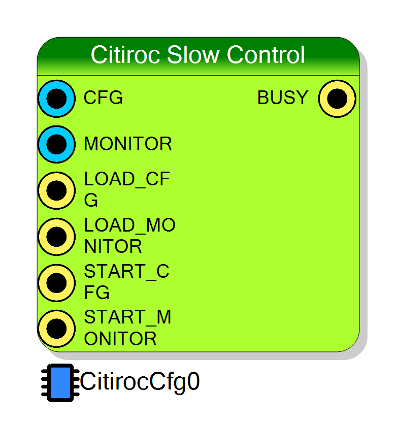
Serial programmer for the CITIROC 1A slow-control chain on the DT5550W-Citiroc1A board. It shifts a 1144-bit configuration word (or a 256-bit probe/monitor word) into the ASIC over the five dedicated slow-control lines, and can take that word from three independent sources: a compile-time default baked into the bitstream, 36 registers written by the host over the readout bus, or a 1144-bit fabric pin.
Introduction
Principle of Operation
The CITIROC 1A is configured through a plain shift register: the FPGA presents one
bit at a time on SR_IN, clocks it with SR_CK, and when all bits are in it pulses
SRLOAD to transfer the shift register into the chip’s configuration latches. The chip
has two such chains, selected by the SELECT line:
- the slow-control register, 1144 bits (
SELECT = '1'); - the probe / monitor register, 256 bits (
SELECT = '0'), which routes internal analog and digital nodes to the monitor outputs.
This block owns that sequence for one ASIC. It drives five board signals that are hard wired to the ASIC pins, and which are therefore not shown on the symbol:
| Component port | Board signal | ASIC pin |
|---|---|---|
CITIROC_CLK |
<ASIC>_SR_CK_s |
SR_CK |
CITIROC_MOSI |
<ASIC>_SR_IN_s |
SR_IN |
CITIROC_SLOAD |
<ASIC>_SRLOAD_s |
SRLOAD |
CITIROC_RESETB |
<ASIC>_RESETB_SR_s |
RESETB_SR |
CITIROC_SELECT |
<ASIC>_SELECT_s |
SELECT |
<ASIC> is the letter chosen in the ASIC property (A, B, C or D).
The bit period is fixed by the Halfbit generic of CitirocSlowControl.vhd, which the
compiler never overrides, so it always keeps its VHDL default of 10000. One serial
bit therefore costs
$$ T_{bit} ;=; 2 \cdot Halfbit ;=; 20,000 \ \text{clock cycles} $$
and a full programming cycle takes
$$ T_{prog} ;\approx; N_{bits} \cdot 2 \cdot Halfbit $$
which is 22.88 M cycles ≈ 143 ms for the 1144-bit configuration and
5.12 M cycles ≈ 32 ms for the 256-bit monitor word, when the block runs on the
DT5550W default global clock of 160 MHz. The serial clock itself is
clk / 20000 ≈ 8 kHz. This is a deliberately slow, once-per-run operation - do not
design a per-event path around it.
Pin Description
LOAD_CFG is high. Bit 1143 is the first bit
shifted into the ASIC, bit 0 the last.
Left open it reads as all zeros, which is harmless as long as LOAD_CFG is also open.
LOAD_MONITOR is high. Bit 255 is sent first.
Left open it reads as all zeros.
ASIC_CONFIGURATION. While high, the shadow
register follows the pin and overrides both the compile-time default and anything the
host writes into REG_CFG0..35. While low, the shadow reverts to the compile-time
default every clock.
Must still be high when the transfer starts. Left open it reads '0'.
LOAD_CFG but for the 256-bit monitor word.
Left open it reads '0'.
1 → 0 transition). A pulse of at least two clock cycles
is required. Requests arriving while BUSY is high are ignored.
Left open it reads '0' and never triggers.
SELECT is driven low to address the probe register and RESETB_SR is not
pulsed.
Left open it reads '0'.
SLOAD pulse has been
issued and the FSM is back in idle - roughly N_bits × 2 × 10000 clock cycles.
Use it to gate further start requests. It is cleared by RESET, but note that reset
does not stop the transfer itself.
Properties
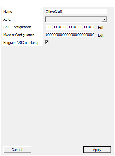
Set the name of the endpoint
Name of the readout-bus endpoint. It becomes the prefix of the generated registers (SCI_REG_<name>_REG_CFG0 …) and of the generated SDK functions
(Citiroc_<name>_CONFIG). Changing it rebuilds the symbol.
Note that the generated Python helper is emitted with the fixed name
Citiroc_CitirocCfg0_CONFIG whatever you put here; only the register names follow.
Default: CitirocCfg0.
Default: CitirocCfg0
Select the ASIC to be connected to the Endpoint
Which of the four CITIROC sites on the board this endpoint drives. It selects the prefix of the board signals the block connects to (A_SR_CK_s, B_SR_CK_s, …), so
one instance per ASIC is needed to configure several chips.
Valid values: A, B, C, D.
Default: A.
Default: A
Options: A B C D
Set the ASIC configuration programmed on startup.
The 1144-character'0'/'1' string programmed into the ASIC at power-up (and used
as the fallback content of the shadow register at every clock). The … button opens
the graphical CITIROC configurator, which returns the string for you.
The configurator is only available in the .NET Framework build of the plugin; in the
CORENET build that code path is compiled out and returns nothing, so the string has to
be entered directly.
In this path character 0 of the string is the first bit shifted out - the opposite
of the SDK download path.
Default: the 1144-bit CAEN reference configuration shipped with the block.
Default: 1110111011101110111011101110111011101110111011101110111011101110111011101110111011101110111011101110111011101110111011101110111011101110111011101110111011101110111011101110111011101110111011101110111011101110111011101110111011101110111011101110111011101110110111111111111111111111111111111111111111111011111100111111101111001111011100000001100000001100000001100000001100000001100000001100000001100000001100000001100000001100000001100000001100000001100000001100000001100000001100000001100000001100000001100000001100000001100000001100000001100000001100000001100000001100000001100000001100000001100000001100000001100000001000100000000000000100000000000000100000000000000100000000000000100000000000000100000000000000100000000000000100000000000000100000000000000100000000000000100000000000000100000000000000100000000000000100000000000000100000000000000100000000000000100000000000000100000000000000100000000000000100000000000000100000000000000100000000000000100000000000000100000000000000100000000000000100000000000000100000000000000100000000000000100000000000000100000000000000100000000000000100000000000111111110100101100010010110011111111111111011
Set the ASIC Monitor Outputs configuration. Configuration will start only upon monitor cfg command
The 256-character'0'/'1' string for the probe / monitor shift register. It is
not programmed at startup: it only reaches the ASIC on a START_MONITOR edge or on
a START_REG_CFG = 2 command.
Default: 256 zeros.
Default: 0000000000000000000000000000000000000000000000000000000000000000000000000000000000000000000000000000000000000000000000000000000000000000000000000000000000000000000000000000000000000000000000000000000000000000000000000000000000000000000000000000000000000000
If true, the ASIC will be programmed after board boodstap with default configuration
When true, the block programs the ASIC once withDefaultConfiguration about
16 777 215 clock cycles (≈ 105 ms at 160 MHz) after reset. When false, the ASIC keeps
its power-up state until something else starts a cycle.
Default: True.
Default: True
⚙️ Detailed Operation
Three sources for the same shift register
Internally the block keeps a shadow copy of the configuration
(ASIC_BITSTREAM_CFG, 1144 bits) and of the monitor word
(ASIC_BITSTREAM_MONITOR, 256 bits). Every clock cycle the shadow is reloaded from
the compile-time default, and three things can overwrite it in the same cycle, in
increasing priority:
every clock: shadow <= CfgDefault (the "ASIC Configuration" property)
if register-file start transition:
shadow <= REG_CFG0 .. REG_CFG35 (host, over the readout bus)
if LOAD_CFG = '1':
shadow <= ASIC_CONFIGURATION (fabric pin, 1144 bits)
The FSM latches the shadow into the shift register at the instant it starts, so the source that was active in that cycle is the one that gets programmed.
What starts a programming cycle
| Trigger | Condition | What is sent |
|---|---|---|
START_CFG pin |
falling edge (the block samples it twice, then looks for 1 → 0) |
1144-bit configuration |
START_MONITOR pin |
falling edge | 256-bit monitor word |
START_REG_CFG register |
transition of bits [1:0] into the value 01 |
1144 bits taken from REG_CFG0..35 |
START_REG_CFG register |
transition of bits [1:0] into the value 10 |
256 bits taken from REG_CFG0..7 |
| power-up | once, if Program ASIC on startup is true | 1144-bit compile-time default |
Because the register path reacts to the transition into a value, the host must write
0 first and then 1 (or 2); writing 1 twice in a row does nothing. The value 11
triggers neither.
The state machine
| State | Action | Wait before the next state |
|---|---|---|
0 idle |
SELECT='1', BUSY='0'. On start: load the shadow, RESETB='0', SLOAD='0', BUSY='1' |
2 × Halfbit |
1 |
release RESETB='1' |
10 × Halfbit |
2 |
drive SR_CK='0' and put bitstream(count) on SR_IN |
Halfbit |
3 |
SR_CK='1' (the ASIC samples here) |
Halfbit |
4 |
SR_CK='0', decrement the bit counter; loop to 2 until the counter reaches 0 |
- |
5 |
SLOAD='1' - transfer the chain into the configuration latches |
4 × Halfbit |
6 |
SLOAD='0', back to idle |
4 × Halfbit |
The counter starts at 1143 and counts down to 0, so the most significant bit of
the 1144-bit word is shifted out first. A monitor cycle is identical except that it
starts the counter at 255, drives SELECT='0' to select the probe register, and does
not pulse RESETB.
BUSY is high for the whole cycle, from the start condition until the FSM returns to
idle. It is the only status output; there is no error or done flag.
Programming at power-up
With Program ASIC on startup = true the block waits 0xFFFFFF = 16 777 215 clock
cycles after reset (≈ 105 ms at 160 MHz), then programs the ASIC once with the
compile-time default. The wait exists so that the board clocks and the ASIC supplies are
settled first. This happens exactly once per reset; it is not repeated.
Bit ordering - read this before you download a bitstream
The same 1144-character string is mapped onto the shift register in opposite directions by the two paths, and this is verified in the sources, not a guess:
- Compile-time default (the ASIC Configuration property): the string is emitted as
a VHDL literal for a
std_logic_vector(1143 downto 0), so character 0 becomes bit 1143 and is therefore the first bit shifted out. - Host / SDK download: the generated helper builds
bit[k] = incfg[k], packs 32 bits per register, and the FSM sends bit 1143 first, so character 0 is the last bit shifted out.
In other words a string that is correct as the startup default is bit-reversed with respect to the same string pushed through the registers. Which of the two matches what the ASIC expects cannot be established from the code in this repository - check against a known-good configuration on real hardware before trusting either.
Register map (endpoint EndpointName)
| Register | Access | Meaning |
|---|---|---|
REG_CFG0 … REG_CFG35 |
write | the 1144-bit configuration, 32 bits per register. REG_CFG35 contributes only its lower 24 bits (32 × 35 + 24 = 1144). For a monitor download only REG_CFG0..7 (256 bits) are used. |
START_REG_CFG |
write | bits [1:0]: 01 = program configuration, 10 = program monitor. Acts on the transition into the value. |
The SDK exposes them as SCI_REG_<EndpointName>_REG_CFG<n> and
SCI_REG_<EndpointName>_START_REG_CFG.
SciSDK usage
The compiler emits two C helpers, Citiroc_<EndpointName>_CONFIG(char *incfg, NI_HANDLE *handle)
and Citiroc_<EndpointName>_CONFIG_MON(char *incfg, NI_HANDLE *handle), plus a Python
equivalent. Both take an ASCII string of '0' / '1' characters (1144 characters for the
configuration, 256 for the monitor), pack it into 32-bit words and end with the
0 → 1 → 0 (or 0 → 2 → 0) sequence on START_REG_CFG.
Messages printed by the compiler
Generating HDL code For <designator>- informational.Generating memory mapped component: <EndpointName>- informational.SDK starting code generation,SDK[C] adding function: Citiroc_<name>_CONFIG- informational.SDK address undefined for <EndpointName>- error, the endpoint did not get a base address; the compilation stops.
Practical recipe
- Leave all six inputs unconnected (an unconnected input pad is tied to zeros, so
LOAD_CFG/START_CFGare inactive) and let Program ASIC on startup load the configuration built in the editor. - To change the configuration at run time, use the register path from the host.
- Use the
CFG/LOAD_CFG/START_CFGpins only when the FPGA logic itself has to choose the configuration - for instance switching between two stored settings. Gate the next request withBUSY.
Resources & Timing
-
Latency: ≈ N_bits × 2 × 10000 clock cycles (22.88 M ≈ 143 ms for the 1144-bit configuration, 5.12 M ≈ 32 ms for the 256-bit monitor word, at the 160 MHz board default clock)
-
Throughput: One serial bit every 20 000 clock cycles (≈ 8 kHz serial clock at 160 MHz); one programming cycle at a time, serialised by BUSY
- The
Halfbitgeneric is fixed at 10000 by the VHDL default; the compiler does not expose it, so the serial rate cannot be changed from the editor. - The block instantiates
CitirocSlowControl.vhdonly - no ADC, no FIFO, no BRAM. - The power-up delay counter and the startup-done flag are the only state cleared by
RESET.