
AND Reduce
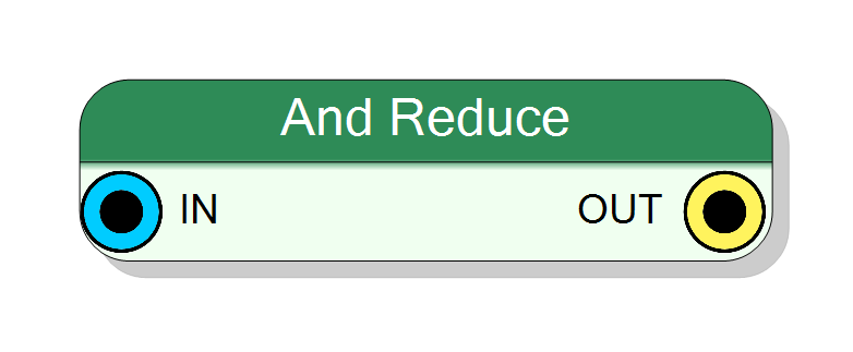
Reduces a multi-bit input vector to a single bit using AND operation. Output is 1 only if all input bits are 1, otherwise 0. Useful for checking if all bits in a vector are set. Pure combinational logic (zero latency).
Introduction
This block implements an AND reduction operation on a multi-bit input vector. It performs a logical AND across all bits of the input, producing a single-bit output.
The output is 1 (HIGH or True) only if all input bits are 1. If the input vector contains at least one 0, the output will be 0 (LOW or False).
The operation is purely combinational with zero clock latency:
$$ \mathrm{OUT} = \mathrm{IN}[0] \land \mathrm{IN}[1] \land \ldots \land \mathrm{IN}[N-1], $$
where $\land$ represents the logical AND operation and $N$ is the input bit width.
Pin Description
Properties
Functional description
The component implements an AND reduction operation in VHDL. It takes a multi-bit input vector and reduces it to a single bit by AND-ing all bits together:
$$ y = \bigwedge_{i=0}^{N-1} x[i], $$
where:
- $x[i]$ → bit $i$ of the input vector
- $y$ → single-bit output
- $\bigwedge$ → AND reduction operator
This is equivalent to checking if all bits are 1 in the input vector:
| Input Pattern | Output |
|---|---|
| All 1s | 1 |
| Any 0 | 0 |
Example
Given an 8-bit input:
11111111→ Output:1(all bits are 1)11111110→ Output:0(at least one bit is 0)10101010→ Output:0(multiple bits are 0)
Mathematical background
The AND reduction operation is a unary operator that combines all bits of a vector using the AND operation. It is commonly used in VHDL/Verilog for:
- Checking if all bits in a vector are set (all-ones detection)
- Validating that all enable signals are active
- Implementing “all true” conditions
Timing
The component is purely combinational with zero latency:
| Property | Latency (clock cycles) |
|---|---|
| AND Reduce | 0 |
The output changes immediately (after propagation delay) when the input changes.
Typical use cases
- All-ones detection in data validation
- Checking if all enable signals are active
- Implementing “all conditions met” logic
- Bit-width reduction in control logic
- Status flag consolidation (all flags must be set)