
Constant Floating-Point [TM]
Time-multiplexed constant floating-point source compliant with IEEE-754. Generates floating-point values across multiple TM phases (1-32). Supports single-precision (32-bit) and double-precision (64-bit) formats. Can provide same value for all phases or different values per phase. Zero latency.
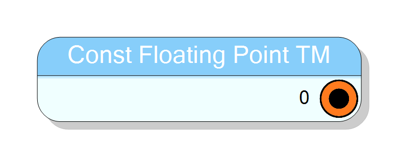
Introduction
This block generates constant floating-point values for time-multiplexed (TM) data streams conforming to the IEEE-754 standard. It produces floating-point constants across multiple TM phases, with each phase receiving its own configurable value in binary IEEE-754 representation.
The component supports two operating modes:
- Same value for all phases: One constant replicated across all TM phases
- Different values per phase: Unique constant for each TM phase
Two precision modes are available:
- IEEE-754 SINGLE: 32-bit format (1 sign + 8 exponent + 23 mantissa bits)
- IEEE-754 DOUBLE: 64-bit format (1 sign + 11 exponent + 52 mantissa bits)
The output is purely combinational with zero clock latency, suitable for direct use in TM floating-point arithmetic pipelines.
Pin Description
Constant floating-point output in IEEE-754 binary format, always TM (time-multiplexed).
Width: BitSize × TM Factor bits, where:
- BitSize = 32 bits (IEEE-754 SINGLE)
- BitSize = 64 bits (IEEE-754 DOUBLE)
Each TM phase occupies a contiguous slice containing a bit-accurate IEEE-754 representation of the specified floating-point value. The output is combinational (zero latency) and available immediately after FPGA configuration.
TM phase ordering: Phase 0 occupies LSBs, Phase N-1 occupies MSBs.
Properties
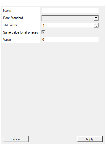
Set the name of the constant. Can be left blank
Optional custom label for the component. If specified, replaces the default title “Const Floating Point TM” on the schematic symbol. Leave blank to use default.Set floating point standard between SINGLE and DOUBLE
IEEE-754 precision standard for all phases. Choose “IEEE-754 SINGLE” for 32-bit format (~7 digit precision, range ±10^38) or “IEEE-754 DOUBLE” for 64-bit format (~15 digit precision, range ±10^308). Applies to all TM phases.Default: IEEE-754 SINGLE
Options: IEEE-754 SINGLE IEEE-754 DOUBLE
Time Multiplexing factor (number of phases)
Time-multiplexing factor (number of parallel phases). Allowed values: 1 to 32. Determines how many constant values are generated per clock cycle. Must match downstream TM components.Default: 4
Range: 1 – 32
If true, the same constant value is used for all TM phases. If false, specify different values for each phase separated by comma, semicolon or space
If True, use a single Value for all TM phases (replicated). If False, provide exactly TMFactor comma/semicolon/space-separated floating-point values (one per phase). Mismatch causes compilation error.Default: True
Set the value(s) of the constant. If ‘Same for all phases’ is true: Use single floating point value (e.g., 3.14159) If ‘Same for all phases’ is false: Use comma/semicolon/space separated values (e.g., 1.5,2.3,3.7,4.2)
Floating-point constant value(s) in decimal or scientific notation. If SameForAllPhases=True: single value (e.g., 3.14159 or 6.022e23). If SameForAllPhases=False: TMFactor values separated by comma, semicolon, or space (e.g., 1.5,2.3,3.7,4.2 for TM=4). Use comma or period as decimal separator. Values are automatically converted to IEEE-754 binary.Default: 0
Functional description
The component implements a time-multiplexed constant floating-point source in VHDL. For TM Factor = $N$, the output contains $N$ IEEE-754 values:
$$ \mathrm{OUT}(t) = [V_0, V_1, V_2, \ldots, V_{N-1}] $$
where each $V_i$ is a floating-point value encoded in IEEE-754 binary format.
TM Factor and phase assignment
The TM Factor determines the number of parallel constant phases:
| TM Factor | Phases per Clock | Total Output Width (Single) | Total Output Width (Double) |
|---|---|---|---|
| 2 | 2 | 64 bits (32×2) | 128 bits (64×2) |
| 4 | 4 | 128 bits (32×4) | 256 bits (64×4) |
| 8 | 8 | 256 bits (32×8) | 512 bits (64×8) |
| 16 | 16 | 512 bits (32×16) | 1024 bits (64×16) |
| 32 | 32 | 1024 bits (32×32) | 2048 bits (64×32) |
Each phase occupies a contiguous slice of the output bus:
- Single precision: 32 bits per phase
- Double precision: 64 bits per phase
Operating modes
Mode 1: Same value for all phases
When SameForAllPhases = True, a single floating-point value is replicated:
Value: 3.14159
TM Factor: 4
FloatingMode: IEEE-754 SINGLE
Output (128 bits): [3.14159, 3.14159, 3.14159, 3.14159] (all in IEEE-754 binary)
Phase0 Phase1 Phase2 Phase3
Mode 2: Different values per phase
When SameForAllPhases = False, provide comma/semicolon/space-separated values:
Value: 1.0, 2.5, -1.5, 6.022e23
TM Factor: 4
FloatingMode: IEEE-754 DOUBLE
Output (256 bits): [1.0, 2.5, -1.5, 6.022e23] (all in IEEE-754 binary)
Phase0 Phase1 Phase2 Phase3
Important: The number of values must exactly match the TM Factor, or a compilation error will occur.
IEEE-754 format structure
Single precision (32 bits per phase)
| Sign (1) | Exponent (8) | Mantissa (23) |
- Range: $\pm 1.18 \times 10^{-38}$ to $\pm 3.40 \times 10^{38}$
- Precision: ~7 decimal digits
Double precision (64 bits per phase)
| Sign (1) | Exponent (11) | Mantissa (52) |
- Range: $\pm 2.23 \times 10^{-308}$ to $\pm 1.80 \times 10^{308}$
- Precision: ~15 decimal digits
Value format
Each phase value uses standard decimal floating-point notation:
- Standard notation:
3.14159,-2.5,0.001 - Scientific notation:
6.022e23,-1.5e-10,9.81e0 - Special values: Component automatically handles ±0, ±∞, and NaN
All values are automatically converted to IEEE-754 binary representation.
Precision considerations
- Single precision: Suitable for most DSP, graphics, and general floating-point tasks
- Double precision: Required for scientific computing, high-precision numerics, and accumulation-heavy algorithms
Choose the precision based on your application’s accuracy requirements and FPGA resource constraints (double uses 2× the bits per phase).
Implementation details
The VHDL implementation concatenates all phase values into a single bus:
vhdl
signal CONST : STD_LOGIC_VECTOR(TotalWidth-1 downto 0);
CONST <= BinaryString(N-1) & BinaryString(N-2) & ... & BinaryString(0);
where each BinaryString(i) is the IEEE-754 binary representation of phase $i$.
The .NET BitConverter class performs the decimal-to-binary conversion at
compile time, ensuring full IEEE-754 compliance.
Timing
The component is purely combinational with zero latency:
| Property | Latency (clock cycles) |
|---|---|
| Constant Floating-Point [TM] | 0 |
All TM phases are available immediately (no pipeline delay).
Typical use cases
- TM DSP algorithms: Provide constant coefficients for parallel TM filters
- TM mathematical constants: Define π, e, or physical constants for each phase
- TM gain/scaling: Supply floating-point multipliers for multi-channel processing
- TM scientific computing: Store predefined values for parallel simulations
- TM machine learning: Neural network weights or bias values across TM phases
- TM calibration: Per-channel floating-point calibration factors
Example configurations
Example 1: Same value, all phases (TM=4, SINGLE)
Name: "PI"
Value: 3.14159265
FloatingMode: IEEE-754 SINGLE
TMFactor: 4
SameForAllPhases: True
Output (128 bits):
Phase 0: 0x40490FDB (π in IEEE-754 single)
Phase 1: 0x40490FDB
Phase 2: 0x40490FDB
Phase 3: 0x40490FDB
Example 2: Different values per phase (TM=4, DOUBLE)
Value: 1.0, 2.5, -1.5, 0.707
FloatingMode: IEEE-754 DOUBLE
TMFactor: 4
SameForAllPhases: False
Output (256 bits):
Phase 0: 0x3FF0000000000000 (1.0)
Phase 1: 0x4004000000000000 (2.5)
Phase 2: 0xBFF8000000000000 (-1.5)
Phase 3: 0x3FE6A09E667F3BCD (0.707...)
Example 3: Scientific notation (TM=2, DOUBLE)
Value: 6.022e23, -1.602e-19
FloatingMode: IEEE-754 DOUBLE
TMFactor: 2
SameForAllPhases: False
Use case: Avogadro's number and electron charge constants
Example 4: Filter gains (TM=8, SINGLE)
Value: 1.0, 0.5, 0.25, 0.125, 0.0625, 0.03125, 0.015625, 0.0078125
FloatingMode: IEEE-754 SINGLE
TMFactor: 8
SameForAllPhases: False
Use case: 8-channel exponentially decaying gain stages