
Spectrum (1D Histogram)
1D histogram block that accumulates input values into configurable bins. When connected to energy signals (QDC, MCA, Peak Sense), it computes the energy spectrum. Supports rebinning, count/time limits, and real-time readout.
Introduction
Principle of Operation
The Spectrum block implements a 1D histogram that accumulates input values into discrete bins. When connected to an energy measurement block (QDC, MCA, Peak Sense), it computes the energy spectrum on the FPGA in real-time.
Let:
- $N$ = number of bins (32 to 16384)
- $B$ = bits per bin (8 to 32, determines maximum counts per bin)
- $x$ = 16-bit input value (0 to 65535)
Each time STROBE goes HIGH, the input DATA value is used as the bin address and that bin’s counter is incremented:
$$ histogram[x] = histogram[x] + 1 $$
The histogram can be read via Resource Explorer or programmatically using SciSDK.
SciSDK Documentation: https://nuclearinstruments.github.io/SCISDK/
Pin Description
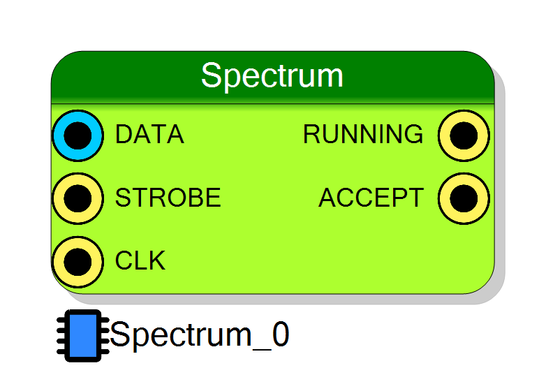
Data Input – 16-bit unsigned input value representing the histogram address.
When connected to an energy measurement (QDC, MCA, Peak Sense), this represents the energy value used to build the energy spectrum.
Strobe – When HIGH (and RUNNING is HIGH), the value on DATA is accumulated into the corresponding histogram bin.
Connect to the data valid (DV) output of the upstream processing block.
Running – HIGH when acquisition has been started via software.
Use this signal to gate upstream logic when the histogram is not active.
Accept – Pulses HIGH for one clock cycle each time a value is successfully accumulated into the histogram.
Can be used for counting accepted events or for debugging.
Properties
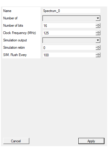
Set the name of the endpoint
Logical endpoint name used in register map. Used in Resource Explorer and SciSDK. Default: Spectrum_0Default: Spectrum_0
Number of bins in the spectrum
Number of bins in the histogram. Available values: 32, 64, 128, 256, 512, 1024, 2048, 4096, 8192, 16384.
More bins provide better resolution but use more FPGA memory. Default: 1024
Default: 1024
Options: 32 64 128 256 512 1024 2048 4096 8192 16384
Number of bits for each bin
Number of bits per bin (determines maximum counts per bin). Range: 8 to 32 bits.
| Bits | Max Counts |
|---|---|
| 8 | 255 |
| 16 | 65,535 |
| 24 | 16,777,215 |
| 32 | 4,294,967,295 |
Default: 16
Default: 16
Range: 8 – 32
Frequency of the input clock
Clock frequency in MHz. Used for time limit calculations. Default: 125 MHzDefault: 125
What the block does with its input WHEN THE PROJECT IS SIMULATED (it has no effect on the synthesized design). None: the block does nothing, as it has always done. Event list: every strobed input value is written to a text file, one ‘<time_ns>
What the block writes to disk when the project is simulated. It has no effect on the synthesized design.
| Value | Effect |
|---|---|
| None | Nothing is written (default). |
| Event list | One <time_ns> <energy> line per strobed input value. |
| Histogram | The <bin> <counts> histogram, binned like the hardware does. |
The file is written to the project’s sim_results folder as <page>_<endpoint>.txt
(<endpoint>.txt on the top page). The path is printed in the compiler log.
Default: None
Default: None
Options: None Event list Histogram
Rebin factor used by the ‘Histogram’ simulation output: bin = min(DATA, 16383) » rebin, wrapped on the number of bins. It replaces the CONFIG_REBIN register, which no software writes during a simulation. Ignored by the other simulation output modes.
Rebin factor used by the Histogram simulation output: $bin = \min(DATA, 16383) » rebin$, wrapped on the number of bins.
It stands in for the CONFIG_REBIN register, which no software writes during a
simulation. Ignored by the other simulation output modes.
Range: 0 to 7. Default: 0
Default: 0
Range: 0 – 7
How many accepted events the simulation output waits before writing to disk. VHDL has no end-of-simulation hook, so the file cannot simply be written once at the end. In ‘Histogram’ mode a flush rewrites the whole file, so flushing after every event is very slow: the default of 100 trades the last partial batch for speed. Lower it to 1 to never lose anything, raise it on large spectra. The file is flushed anyway as soon as the event stream goes quiet, so a run with fewer events than this still produces complete data.
How many accepted events the simulation output waits before writing to disk. VHDL has no end-of-simulation hook, so the file cannot simply be written once at the end of the run.
In Histogram mode a flush rewrites the whole file, so flushing after every event is very slow. The default of 100 trades the last partial batch for speed; set it to 1 to never lose anything, raise it on large spectra.
The file is flushed anyway as soon as the event stream goes quiet, so a run with fewer events than this still produces complete data.
Default: 100
Default: 100
⚙️ Detailed Operation
Data Flow
┌──────────────────────────────────────────────────────────────────┐
│ Spectrum Data Flow │
│ │
│ DATA (16-bit) ───►┌──────────────┐ │
│ │ │ ┌─────────────┐ │
│ STROBE ──────────►│ Histogram │────►│ Memory │───► PC │
│ │ Accumulator │ │ (N bins) │ │
│ CLK ─────────────►│ │ │ │ │
│ └──────────────┘ └─────────────┘ │
│ │ │
│ ┌────┴────┐ │
│ │ RUNNING │──► HIGH when acquisition active │
│ │ ACCEPT │──► Pulse when value accepted │
│ └─────────┘ │
└──────────────────────────────────────────────────────────────────┘
Accumulation Process
- Software starts acquisition via CONFIG register
- When STROBE goes HIGH and RUNNING is HIGH:
- The value on DATA is used as the bin index
- That bin’s counter is incremented by 1
- ACCEPT pulses HIGH for one clock cycle
- Data accumulates until:
- Software stops acquisition, OR
- Count limit is reached (if configured), OR
- Time limit is reached (if configured)
Timing Diagram
Bin Addressing and Rebinning
With rebin = 0, the 16-bit input value is used directly as the bin address. If the value exceeds the number of bins, it saturates to the last bin.
| Rebin | Formula | Effective Bins | Values per Bin |
|---|---|---|---|
| 0 | DATA | 65536 (or configured) | 1 |
| 1 | DATA » 1 | 32768 | 2 |
| 2 | DATA » 2 | 16384 | 4 |
| 3 | DATA » 3 | 8192 | 8 |
| 4 | DATA » 4 | 4096 | 16 |
| 5 | DATA » 5 | 2048 | 32 |
| 6 | DATA » 6 | 1024 | 64 |
| 7 | DATA » 7 | 512 | 128 |
Formula: $bin_{index} = DATA » rebin$
Saturation: If $bin_{index} \geq N_{bins}$, the value is accumulated in the last bin ($N_{bins} - 1$).
Acquisition Limits
The spectrum supports three acquisition modes:
| Mode | Description | CONFIG_LIMIT Setting |
|---|---|---|
| Free-running | No limit, runs until stopped | 0 |
| Count limit | Stops after N total events | (1 << 30) + count |
| Time limit | Stops after T milliseconds | (1 << 31) + time_ms |
When a limit is reached, acquisition automatically stops and the histogram is frozen.
Overflow Handling
If a bin reaches maximum counts ($2^B - 1$), it saturates and does not wrap around. The maximum counts per bin depends on the Number of bits property:
| Bits | Max Counts per Bin |
|---|---|
| 8 | 255 |
| 16 | 65,535 |
| 24 | 16,777,215 |
| 32 | 4,294,967,295 |
Configuration Registers
CONFIG
| Bit | Function |
|---|---|
| 0 | Flush (clear) histogram |
| 1 | Reset |
| 2 | Start acquisition |
CONFIG_LIMIT
| Bits | Function |
|---|---|
| 28:0 | Limit value (counts or ms) |
| 30 | Count limit enable |
| 31 | Time limit enable |
CONFIG_REBIN
Rebin factor (0-7). Higher values combine more input values per bin.
STATUS
| Bit | Function |
|---|---|
| 0 | Running (1 = acquisition active) |
Software Integration with SciSDK
The Spectrum is fully supported by SciSDK. For complete documentation see: SciSDK Spectrum Guide
Available Parameters
| Parameter | Access | Description | Default |
|---|---|---|---|
rebin |
R/W | Rebinning factor (0-7) | 0 |
limitmode |
R/W | freerun, total_count, time |
freerun |
limit |
R/W | Limit value (counts or seconds) | 0 |
acq_mode |
R/W | blocking or non-blocking |
blocking |
timeout |
R/W | Timeout in ms for blocking mode | 1000 |
Available Commands
| Command | Description |
|---|---|
start |
Start acquisition |
stop |
Stop acquisition |
reset |
Clear histogram and reset counters |
Buffer Structure
c
typedef struct {
uint32_t magic; // Buffer type identifier
uint32_t *data; // Histogram bin counts
struct {
uint32_t buffer_size; // Number of bins
uint32_t total_bins; // Total bins in FPGA
uint32_t valid_bins; // Valid bins read
} info;
} SCISDK_SPECTRUM_DECODED_BUFFER;
C/C++ Example
c
#include "SciSDK_DLL.h"
// Allocate buffer
SCISDK_SPECTRUM_DECODED_BUFFER *buffer;
SCISDK_AllocateBuffer("board0:/MMCComponents/Spectrum_0",
T_BUFFER_TYPE_DECODED,
(void**)&buffer, _sdk);
// Configure: 1024 bins, count limit of 100000 events
SCISDK_SetParameterInteger("board0:/MMCComponents/Spectrum_0.rebin", 4, _sdk);
SCISDK_SetParameterString("board0:/MMCComponents/Spectrum_0.limitmode",
"total_count", _sdk);
SCISDK_SetParameterInteger("board0:/MMCComponents/Spectrum_0.limit", 100000, _sdk);
// Reset and start
SCISDK_ExecuteCommand("board0:/MMCComponents/Spectrum_0.reset", "", _sdk);
SCISDK_ExecuteCommand("board0:/MMCComponents/Spectrum_0.start", "", _sdk);
// Read spectrum (blocking until limit reached or timeout)
SCISDK_SetParameterString("board0:/MMCComponents/Spectrum_0.acq_mode",
"blocking", _sdk);
SCISDK_SetParameterInteger("board0:/MMCComponents/Spectrum_0.timeout",
10000, _sdk); // 10 seconds
int ret = SCISDK_ReadData("board0:/MMCComponents/Spectrum_0",
(void*)buffer, _sdk);
if (ret == NI_OK) {
// Find peak channel
uint32_t max_counts = 0;
int peak_bin = 0;
for (int i = 0; i < buffer->info.valid_bins; i++) {
if (buffer->data[i] > max_counts) {
max_counts = buffer->data[i];
peak_bin = i;
}
}
printf("Peak at bin %d with %u counts\n", peak_bin, max_counts);
// Calculate total integral
uint64_t total = 0;
for (int i = 0; i < buffer->info.valid_bins; i++) {
total += buffer->data[i];
}
printf("Total counts: %llu\n", total);
}
// Stop and free
SCISDK_ExecuteCommand("board0:/MMCComponents/Spectrum_0.stop", "", _sdk);
SCISDK_FreeBuffer("board0:/MMCComponents/Spectrum_0",
T_BUFFER_TYPE_DECODED, (void**)&buffer, _sdk);
Python Example
python
from scisdk.scisdk import SciSDK
import matplotlib.pyplot as plt
import numpy as np
sdk = SciSDK()
sdk.AddNewDevice("usb:10500", "dt5560", "board0", "RegisterFile.json")
# Allocate buffer
res, buf = sdk.AllocateBuffer("board0:/MMCComponents/Spectrum_0",
sdk.T_BUFFER_TYPE_DECODED)
# Configure: 1024 bins, 10 second time limit
sdk.SetParameter("board0:/MMCComponents/Spectrum_0.rebin", 4)
sdk.SetParameter("board0:/MMCComponents/Spectrum_0.limitmode", "time")
sdk.SetParameter("board0:/MMCComponents/Spectrum_0.limit", 10) # 10 seconds
# Reset and start
sdk.ExecuteCommand("board0:/MMCComponents/Spectrum_0.reset", "")
sdk.ExecuteCommand("board0:/MMCComponents/Spectrum_0.start", "")
# Wait and read
sdk.SetParameter("board0:/MMCComponents/Spectrum_0.acq_mode", "blocking")
sdk.SetParameter("board0:/MMCComponents/Spectrum_0.timeout", 15000)
res, buf = sdk.ReadData("board0:/MMCComponents/Spectrum_0", buf)
if res == 0:
# Plot spectrum
plt.figure(figsize=(12, 6))
plt.bar(range(len(buf.data)), buf.data, width=1.0)
plt.xlabel("Bin (Channel)")
plt.ylabel("Counts")
plt.title("Energy Spectrum")
plt.yscale('log') # Log scale for better visualization
plt.grid(True, alpha=0.3)
plt.show()
# Print statistics
total = sum(buf.data)
peak_bin = np.argmax(buf.data)
print(f"Total counts: {total}")
print(f"Peak channel: {peak_bin} ({buf.data[peak_bin]} counts)")
sdk.ExecuteCommand("board0:/MMCComponents/Spectrum_0.stop", "")
Simulation Output
In the synthesized design the histogram is read back over the register bus. During a
project simulation there is no software to do that, so the block can instead dump
what it sees to a text file in the project’s sim_results folder, next to the waveform
dump. The Simulation output property selects what is written:
| Mode | File content |
|---|---|
| None (default) | Nothing is written. |
| Event list | One <time_ns> <energy> line per strobed input value. |
| Histogram | The accumulated <bin> <counts> histogram, binned the same way the hardware bins it. |
The file is named <page>_<endpoint>.txt, or just <endpoint>.txt when the block sits
on the top page, and its full path is printed in the compiler log. It is rewritten from
scratch every time it changes, so it is complete even if the simulation is stopped early.
Since no software writes CONFIG_REBIN during a simulation, the Simulation rebin
property supplies the rebin factor used by the Histogram mode.
This affects the simulation model only: the synthesized design is bit-identical whatever the two properties are set to.
When the data reaches disk
There is no end-of-simulation hook in VHDL, so the file is flushed every SIM. Flush Every accepted events (100 by default) rather than written once at the end. In Histogram mode a flush rewrites the whole file, which is why flushing after every event is not the default — the price is the last partial batch.
As a safety net the file is also flushed as soon as the event stream goes quiet (256 write clocks with no event), so short runs and runs whose stimulus ends before the simulation does still produce complete data. You only lose events if they are still arriving when the simulation stops.
Resource Explorer
The Spectrum tool in Resource Explorer provides real-time histogram visualization with linear/logarithmic scale, zoom, and statistics display.
Quick Reference
| Item | Description |
|---|---|
| Input | 16-bit unsigned value |
| Bins | 32 to 16384 |
| Counts per bin | 8 to 32 bits |
| Acquisition modes | Free-run, count limit, time limit |
| Rebinning | 0-7 (divides bins by 2^rebin) |
| Best for | Energy spectra, amplitude distributions |
Resources & Timing
-
Latency: 2-3 clock cycles from STROBE to bin update
-
Throughput: One accumulation per clock cycle
- Uses BRAM for histogram storage
- Bin saturation prevents overflow wrap-around
- Supports real-time readout during acquisition
- Time limit resolution depends on clock frequency
- Can be connected to QDC/MCA/Peak Sense for energy spectra