
RF CIC + Compensator Decimator
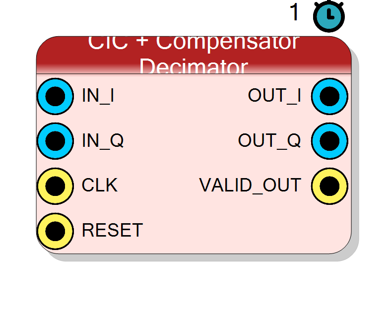
A complete complex I/Q down-sampling stage: a multiplier-free CIC decimator by R, followed by a short compensation FIR running at the low output rate that cancels the CIC’s sinc^N passband droop, adds stop-band attenuation, and normalises the DC gain to unity. One drop-in block that turns the cheap-but-droopy CIC into a flat-passband channel decimator - the workhorse rate-reduction stage of a DDC.
Introduction
The CIC + Compensator Decimator chains two filters inside one HLS core (I and Q processed independently):
x[n] ─► [ CIC decimator ↓R ] ─► [ compensation FIR ] ─► y[m]
sinc^N, multiplier-free inverse-sinc^N + LPF
(Fs_in -> Fs_out) (runs at Fs_out)
-
CIC decimator - N cascaded integrators at the input rate, a divide by R, then N cascaded combs at the output rate. Exactly the structure of
cic_decim, using no multipliers:H_cic(z) = [ (1 - z^-(R*M)) / (1 - z^-1) ]^N |H_cic(f)| = | sin(pi*R*M*f/Fs_in) / sin(pi*f/Fs_in) |^N -
Compensation FIR - a short symmetric FIR that runs at the low output rate (so only
COMP_TAPSreal MACs per output sample). Its magnitude response is the inverse of the CIC droop across the passband, then a cosine roll-off into a stop-band. The FIR coefficients are computed by the plugin at design time (see below) and baked into the netlist.
The result on OUT_I/OUT_Q is a flat-passband, unity-DC-gain,
well-anti-aliased complex baseband stream at Fs_out = Fs_in / R.
For the bare CIC without compensation see Component_CICDecimator
(cic_decim).
Pin Description
Fs_in. Signed,
Input Bit Width bits.
Fs_in. Signed,
Input Bit Width bits. Tie to zero for a real-only signal.
Fs_in.
Default: Acquisition clock.
Fs_out = Fs_in / R.
Signed, Output Bit Width bits, unity DC gain. Valid only when
VALID_OUT is high.
OUT_I.
R clocks on
the cycle where OUT_I/OUT_Q carry a fresh sample.
Properties
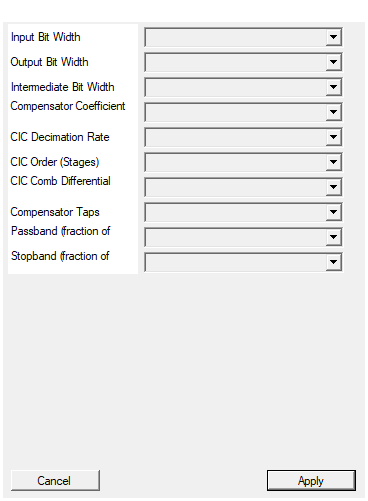
Bit width of each I/Q input sample (signed).
Bit width of each signed I / Q input sample. Range 4 to 32, default 16. Redesign on change.Default: 16
Options: 4 5 6 7 8 9 10 11 12 13 14 15 16 17 18 19 20 21 22 23 24 25 26 27 28 29 30 31 32
Bit width of each I/Q output sample (signed).
Bit width of each signed I / Q output sample (after the compensator and theCOMP_SHIFT down-scale). Range 8 to 40, default 24.
Redesign on change.
Default: 24
Options: 8 9 10 11 12 13 14 15 16 17 18 19 20 21 22 23 24 25 26 27 28 29 30 31 32 33 34 35 36 37 38 39 40
Bit width of the signal between CIC and compensator.
Bit width of the signal handed from the CIC to the compensator FIR. Set it at least as wide as the CIC internal width (InputSize + N*ceil(log2(R*M))) to avoid truncating CIC LSBs. Choices
20, 24, 28, 32, 36, 40, 48, default 32. Redesign on change.
Default: 32
Options: 20 24 28 32 36 40 48
Bit width of the compensator coefficients (signed).
Bit width of each signed compensator coefficient. A larger value lowers the stop-band error floor at the cost of DSP width. The plugin picks the power-of-two quantisation scale2^COMP_SHIFT so the peak coefficient
fits this width with ~10% headroom. Choices 12, 14, 16, 18, 20, 24,
default 18.
Default: 18
Options: 12 14 16 18 20 24
Decimation ratio R. Output rate = input rate / R.
CIC decimation factor R (Fs_out = Fs_in / R). Choices 2, 4, 8,
16, 32, 64, 128, 256, 512, 1024, default 8.
Default: 8
Options: 2 4 8 16 32 64 128 256 512 1024
Number of integrator/comb stages in the CIC.
CIC order N (number of integrator/comb stages). Higher N deepens alias rejection and steepens the droop the compensator must invert. Choices 1..6, default 3.Default: 3
Options: 1 2 3 4 5 6
Usually 1.
CIC comb differential delay M (output-rate samples). Almost always 1;M=2 widens the stop-band notches. Choices 1, 2, default
1.
Default: 1
Options: 1 2
Number of taps in the compensator FIR. Odd numbers only. 21..41 typical.
Number of taps in the compensator FIR (odd values; the plugin bumps an even value up by one to keep linear-phase symmetry). More taps sharpen the transition and lower ripple at the cost of DSPs. Choices 11, 15, 21, 31, 41, 51, 63, default 21. 21-41 is typical.Default: 21
Options: 11 15 21 31 41 51 63
Upper edge of the flat passband, as a fraction of the OUTPUT Nyquist (Fs_out/2). Typical 0.6 .. 0.8.
Upper edge of the flat (inverse-sinc-corrected) passband, as a fraction of the output NyquistFs_out/2. Keep this below where the CIC
droop becomes uncorrectable. Choices 0.4, 0.5, 0.6, 0.7, 0.8, 0.9,
default 0.7.
Default: 0.7
Options: 0.4 0.5 0.6 0.7 0.8 0.9
Lower edge of the stopband. Must be > PassbandFrac and <= 1. Typical 0.9 .. 1.0.
Lower edge of the compensator stop-band, as a fraction ofFs_out/2.
Must be greater than PassbandFrac and <= 1 (validated at compile
time). The passband-to-stopband gap is the cosine transition band.
Choices 0.75, 0.85, 0.9, 0.95, 1.0, default 0.95.
Default: 0.95
Options: 0.75 0.85 0.9 0.95 1.0
Usage
Why a compensation FIR follows the CIC
A CIC is cheap but its passband droops (the sinc^N shape falls toward
the band edge) and its stop-band nulls are shallow for small N. Because the
CIC has already reduced the rate to Fs_out, the correction can be done
by a short FIR at the low rate - far cheaper than filtering at Fs_in.
The compensator does three jobs at once:
- Droop correction : an inverse-sinc^N response over the passband
flattens
|H_cic| * |H_comp|to ~unity. - Extra selectivity : a cosine transition from the passband edge to a user stop-band adds attenuation the CIC alone cannot provide.
- Gain normalisation : the coefficient DC gain is set to
1/(R*M)^Nso the CIC’s(R*M)^Ngain cancels and the chain is unity DC gain (unlike the barecic_decim, whose output carries the full CIC gain).
Compensator design (done in the plugin, baked in)
The plugin (Component_CICCompDecim) designs the FIR by frequency
sampling on a 512-point grid over [0, Fs_out/2], then an inverse DTFT
(cosine sum, exploiting the real-even symmetry) and a Hamming window. The
target magnitude at output-normalised frequency f_o (with f_o = 1 at
Fs_out/2) is:
passband (f_o <= PassbandFrac):
H_target = (R*M)^N / |H_cic(f_o)| # exact inverse of CIC droop
transition (PassbandFrac < f_o <= StopbandFrac):
t = (f_o - PassbandFrac) / (StopbandFrac - PassbandFrac)
H_target = 0.5 * (1 + cos(pi * t)) # cosine roll-off 1 -> 0
stopband (f_o > StopbandFrac):
H_target = 0
The impulse response is then forced symmetric (linear phase), Hamming
windowed, and DC-normalised so sum(h) = 1/(R*M)^N.
Coefficient quantisation and the output shift
The real coefficients are quantised with a power-of-two scale
2^COMP_SHIFT, where COMP_SHIFT is chosen automatically so the largest
|h| fills the signed CoefSize word with ~10% headroom:
COMP_SHIFT = floor( log2( 0.9 * (2^(CoefSize-1)) / max|h| ) ) (>= 1)
h_int[k] = round( h[k] * 2^COMP_SHIFT ) clipped to CoefSize bits
The FIR accumulates in a wide INTERM_SIZE + CoefSize + 8-bit accumulator,
then the result is arithmetic-right-shifted by COMP_SHIFT and truncated
to OutputSize. Because the coefficients already encode the 1/(R*M)^N
DC target, this restores unity DC gain of the full chain.
Bit widths (all user-selectable here)
Unlike the plain CIC (whose output width is forced by bit growth), this block lets you pick the widths explicitly and truncates between stages:
CIC internal width : InputSize + N*ceil(log2(R*M)) (bit-true, no overflow)
CIC -> comp : truncated to IntermSize bits
comp accumulator : IntermSize + CoefSize + 8 bits (absorbs the tap sum)
output : OutputSize bits (after >> COMP_SHIFT and truncation)
Worked example (defaults N=3, R=8, M=1, InputSize=16):
CIC growth = 3 * ceil(log2(8)) = 9 bits
CIC internal = 16 + 9 = 25 bits (then truncated to IntermSize = 32)
comp acc = 32 + 18 + 8 = 58 bits
output = OutputSize = 24 bits, unity DC gain
Choose IntermSize wide enough to preserve the CIC’s LSBs
(>= InputSize + N*ceil(log2(R*M)) keeps it lossless; the default 32 is
ample for the common cases). OutputSize sets the final precision.
VALID_OUT strobe timing
The block takes one input pair per clock and emits a new decimated,
compensated sample once every R clocks. VALID_OUT is a one-clock-wide
strobe marking the cycle where OUT_I/OUT_Q are fresh; both the CIC comb
update and the compensator MAC fire together on that tick. Between strobes
the outputs hold. Qualify downstream capture with VALID_OUT.
CLK _|‾|_|‾|_ ... (R clocks) ... _|‾|_
VALID_OUT __|‾|____ ... ...__|‾|_
^ CIC comb + compensator MAC both fire here
Timing, interface and reset
#pragma HLS PIPELINE II=1: one input sample pair per clock.- The compensator MAC is fully unrolled (
COMP_TAPSDSPs per channel) but only clocks its result on the decimation tick, so throughput stays II=1. - All ports use
ap_none(no handshake). Coefficients are a compile-time constant ROM (no fabric pins). RESET(ap_rst) clears the CIC integrators/combs, the compensator delay line and the output registers.
Design-time validation
The plugin rejects StopbandFrac <= PassbandFrac with a compile error
(the transition band would be empty/negative). Keep
PassbandFrac < StopbandFrac <= 1.
Typical DDC chain
ADC -> Mixer(x NCO) -> cic_comp_decim -> [FIR channel select] -> DSP/DMA
^ bulk rate reduction + flat passband
For very large total decimation, cascade a cic_comp_decim (or a bare
cic_decim) for the coarse factor with a halfband/FIR chain for the final
sharp channel filtering.
Resources & Timing
-
Latency: Symbol/scheduling latency 1 clock; the first valid output appears after the CIC rate divider fills plus the combined CIC + compensator group delay (~NRM/2 input samples for the CIC, plus (CompTaps-1)/2 output samples for the FIR).
-
Throughput: 1 input sample pair per clock (II=1); one valid output sample every R clocks, flagged by VALID_OUT.
Implemented with Vitis HLS. The CIC part is multiplier-free (2N adders +
2N subtractors per channel, bit-true to InputSize + N*ceil(log2(R*M))).
The compensator adds ~CompTaps DSP48 MACs per channel, but they run at the
low output rate. Coefficients are a compile-time constant ROM designed by
the plugin (inverse-sinc passband + cosine roll-off, Hamming windowed,
symmetric, DC-normalised to 1/(R*M)^N). Output is unity DC gain - no
downstream rescale needed, unlike the bare cic_decim.