
RF NCO (fixed freq)
Numerically Controlled Oscillator that emits a complex I/Q sinusoid at a fixed frequency baked into the netlist at synthesis time. Typical use: local oscillator feeding one input of the RF Mixer for down- or up-conversion.
Introduction
The NCO (fixed freq) block generates a complex tone
OUT_I[n] = A * cos(2*pi * f_norm * n)
OUT_Q[n] = A * sin(2*pi * f_norm * n)
where A = 2^(OutSize-1) - 1 (full-scale signed) and f_norm is the
Output Frequency (normalised to Fs) property.
Internally, a phase accumulator of AccSize bits advances by a
Frequency Tuning Word (FTW) every clock cycle:
FTW = round(f_norm * 2^AccSize) (baked in at synthesis time)
f = FTW / 2^AccSize * Fs (Hz)
The top LutAddrSize bits of the accumulator index two sin/cos ROMs
(pre-computed by the plugin) whose values are read out on the I and Q
ports. The lower accumulator bits provide sub-LUT phase resolution;
they contribute nothing to amplitude but let the FTW sweep the output
frequency in very fine steps.
For a run-time programmable version see Component_NCOProgrammable.
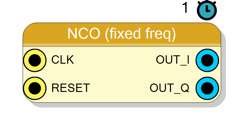
Pin Description
Properties
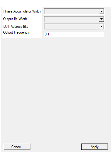
Bit width of the phase accumulator. Sets the frequency resolution : df/Fs = 1 / 2^AccSize.
Bit width of the phase accumulator. Determines the frequency resolutiondf/Fs = 1 / 2^AccSize. Default 32.
Default: 32
Options: 16 20 24 28 32 40 48
Bit width of each I / Q output sample (signed)
Bit width of each signed I / Q output sample. Range 8..24, default 16.Default: 16
Options: 8 9 10 11 12 13 14 15 16 17 18 19 20 21 22 23 24
log2 of the sin/cos LUT depth. Higher values reduce phase-truncation spurs at the cost of BRAM. Default 10 -> 1024 entries.
log2 of the sin/cos ROM depth (ROM entries = 2^LutAddrSize).
Larger values reduce phase-truncation spurs at the cost of BRAM.
Default 10 (1024 entries per ROM, ~60 dB SFDR).
Default: 10
Options: 8 9 10 11 12
Output frequency as a fraction of Fs, ARBITRARY value in 0 .. 0.5 (Nyquist). Type any decimal, e.g. 0.137. FTW = round(NormFreq * 2^AccSize); resolution df/Fs = 1/2^AccSize. Positive rotates the I/Q vector counter-clockwise (I=cos, Q=sin).
Output frequency expressed as a fraction of the sampling frequency Fs. Range 0..0.5 (Nyquist). Default 0.1.Default: 0.1
Usage
Frequency resolution and range
df / Fs = 1 / 2^AccSize (smallest step)
f_max = Fs / 2 (Nyquist)
For AccSize = 32 and Fs = 250 MHz the smallest step is ~0.058 Hz.
Spurious performance
Phase truncation to LutAddrSize bits introduces small spurs at
frequencies related to f_norm. Standard sin/cos ROM guidance:
SFDR ~= 6 * LutAddrSize dB
Default LutAddrSize=10 gives about 60 dB SFDR. Use 12 (SFDR ~72 dB) when the NCO is driving a highly linear datapath and you cannot afford the spurs.
Timing
#pragma HLS PIPELINE II=1: one output pair per clock.- 1-clock latency (accumulator update -> ROM read is one register stage).
- All data ports use
ap_none;FTWis baked in as an internal constant signal, no top-level pin is created.
Reset
RESET is the HLS synchronous reset (ap_rst). The internal phase
accumulator is cleared to zero, so after reset OUT_I starts at +A
and OUT_Q at 0.
Typical applications
- LO for the RF Mixer : wire
OUT_I -> B_IandOUT_Q -> B_Qof the mixer for down-conversion (exp(+j*2*pi*f*n)) or up-conversion. - Test tone generator for characterisation.
- Phase reference for coherent detection.
Resources & Timing
-
Latency: 1 clock cycle
-
Throughput: 1 sample per clock (II=1)
Two BRAMs (or distributed ROMs for LutAddrSize <= 9) hold cos/sin; one adder for the phase accumulator. No multipliers. Because the FTW is a compile-time constant Vivado can often optimise the accumulator down further.