
Fixed P. Accumulator
Running fixed-point accumulator with a synchronous clear. The accumulator keeps its own Q format, so guard bits can be added without changing the input scaling.
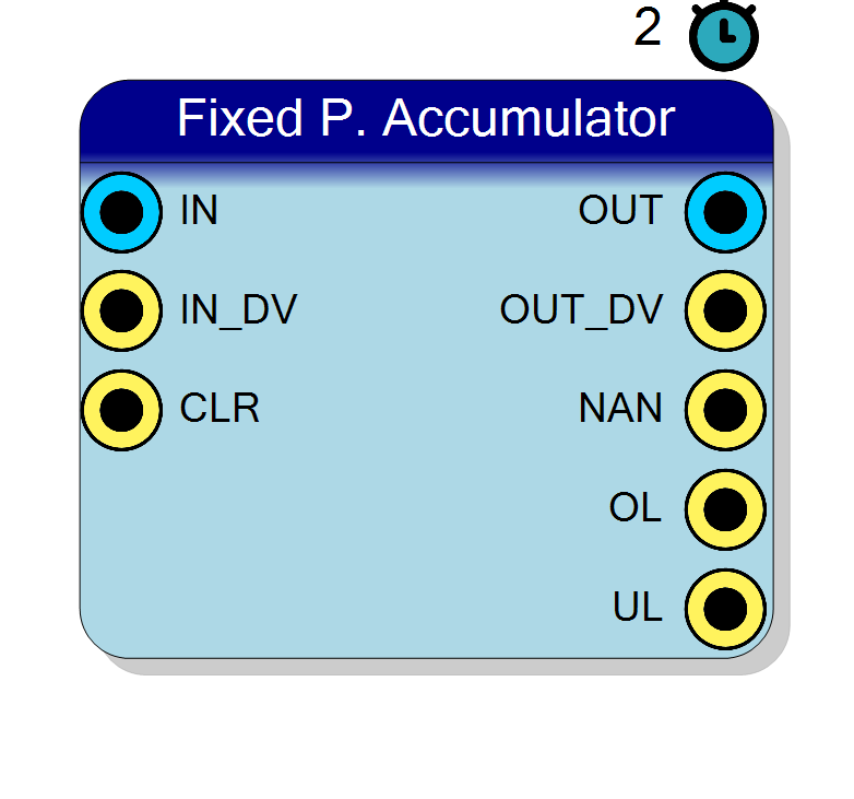
Introduction
The block computes, in fixed-point arithmetic, $$ \mathrm{OUT}(n) = \sum_{k} \mathrm{IN}(k) $$
Every operand and every result carries its own Q format: the number of integer bits, the number of fractional bits and the sign are chosen independently. The binary point is tracked through the whole datapath, so operands with different scaling are aligned automatically – no manual shifting is required, which is the main practical difference with respect to the integer-only arithmetic blocks.
Pin Description
Properties
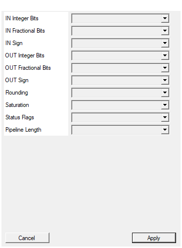
Number of INTEGER bits of IN (the sign, when present, uses one of them).
Number of INTEGER bits of the operandIN (1 to 64). When the port is SIGNED one
of these bits carries the sign.
Default: 16
Options: 1 2 3 4 5 6 7 8 9 10 11 12 13 14 15 16 17 18 19 20 21 22 23 24 25 26 27 28 29 30 31 32 33 34 35 36 37 38 39 40 41 42 43 44 45 46 47 48 49 50 51 52 53 54 55 56 57 58 59 60 61 62 63 64
Number of FRACTIONAL bits of IN, i.e. how many bits sit to the right of the binary point. Total width = integer + fractional bits.
Number of FRACTIONAL bits of the operandIN (0 to 64), i.e. the bits to the right
of the binary point. Total port width = integer + fractional bits.
Default: 0
Options: 0 1 2 3 4 5 6 7 8 9 10 11 12 13 14 15 16 17 18 19 20 21 22 23 24 25 26 27 28 29 30 31 32 33 34 35 36 37 38 39 40 41 42 43 44 45 46 47 48 49 50 51 52 53 54 55 56 57 58 59 60 61 62 63 64
Select whether IN is a signed (two’s complement) or unsigned quantity.
Arithmetic type of IN:
- SIGNED – two’s complement, range $[-2^{N_{int}-1}, 2^{N_{int}-1})$
- UNSIGNED – non negative only, range $[0, 2^{N_{int}})$
Default: SIGNED
Options: UNSIGNED SIGNED
Number of INTEGER bits of OUT (the sign, when present, uses one of them).
Number of INTEGER bits of the resultOUT (1 to 64). When the port is SIGNED one
of these bits carries the sign.
Default: 32
Options: 1 2 3 4 5 6 7 8 9 10 11 12 13 14 15 16 17 18 19 20 21 22 23 24 25 26 27 28 29 30 31 32 33 34 35 36 37 38 39 40 41 42 43 44 45 46 47 48 49 50 51 52 53 54 55 56 57 58 59 60 61 62 63 64
Number of FRACTIONAL bits of OUT, i.e. how many bits sit to the right of the binary point. Total width = integer + fractional bits.
Number of FRACTIONAL bits of the resultOUT (0 to 64), i.e. the bits to the right
of the binary point. Total port width = integer + fractional bits.
Default: 0
Options: 0 1 2 3 4 5 6 7 8 9 10 11 12 13 14 15 16 17 18 19 20 21 22 23 24 25 26 27 28 29 30 31 32 33 34 35 36 37 38 39 40 41 42 43 44 45 46 47 48 49 50 51 52 53 54 55 56 57 58 59 60 61 62 63 64
Select whether OUT is a signed (two’s complement) or unsigned quantity.
Arithmetic type of OUT:
- SIGNED – two’s complement, range $[-2^{N_{int}-1}, 2^{N_{int}-1})$
- UNSIGNED – non negative only, range $[0, 2^{N_{int}})$
Default: SIGNED
Options: UNSIGNED SIGNED
ROUND: round to nearest when discarding fractional bits. TRUNCATE: drop them (cheaper, adds a DC bias).
- ROUND – round to nearest when discarding fractional bits
- TRUNCATE – discard them (cheaper, introduces a negative bias)
Default: ROUND
Options: TRUNCATE ROUND
YES: clip to the largest representable output value on overflow. NO: wrap around (cheaper, but overflow changes sign).
- YES – clip to the largest representable output value on overflow
- NO – wrap around modulo the output width
Default: YES
Options: NO YES
YES: the block exposes three extra 1-bit outputs, valid together with OUT_DV – NAN (the result is mathematically undefined for the operands presented, or the operand had to be clamped into the convergence domain of the algorithm), OL (overflow: the true result left the output format and was saturated), and UL (underflow: the true result was not zero but requantized to zero). NO: the pins are not generated and the logic that produces them is not synthesised.
Default: YES
Options: NO YES
Fixed latency of the block, in clock cycles. More stages ease timing closure. Ignored in SERIAL mode, where the latency is set by the iteration count.
Fixed latency of the block in clock cycles (1 to 8). Higher values ease timing closure without changing the numerical result.Default: 2
Options: 1 2 3 4 5 6 7 8
Functional description
$$ \mathrm{OUT}(n) = \sum_{k} \mathrm{IN}(k) $$
where
IN– input operand, format $Q_{IN_BitsInt.IN_BitsFract}$OUT– result, format $Q_{OUT_BitsInt.OUT_BitsFract}$
Fixed-point format
A value with $N_{int}$ integer bits and $N_{frac}$ fractional bits is stored on $N_{int} + N_{frac}$ bits and represents
$$ \text{value} = \frac{\text{raw integer}}{2^{N_{frac}}} $$
When the operand is SIGNED, one of the integer bits carries the sign (two’s complement). Each port is configured independently, so it is perfectly legal to feed a $Q_{16.0}$ signal and a $Q_{2.14}$ coefficient into the same block.
Implementation
The sum is held in a wide internal register and requantized on the way out. Because the state feeds back and depends on the input, the HLS core is synthesised with config_rtl -reset state so the register cannot latch X in simulation.
Rounding and overflow
Two properties control how the internal full precision result is reduced to the output format:
- Rounding –
ROUNDrounds to nearest when fractional bits are discarded,TRUNCATEsimply drops them. Truncation is cheaper but introduces a systematic negative bias, which accumulates in a long processing chain. - Saturation –
YESclips to the largest representable value,NOwraps around. Wrapping turns a small overflow into a full-scale sign flip, so saturation is strongly recommended for signal processing.
Latency
The PipelineLength property fixes the latency of the block in clock cycles (1 to 8). Raising it helps timing closure at high clock rates and does not change the numerical result. The symbol reports the configured latency.
Typical use cases
- Integrating a signal over a gate
- Charge or energy summation
- Building a running total for averaging