
Timer (Start/Stop)
Programmable timer with explicit start and stop controls. Generates periodic pulses or one-shot events based on configurable target count. Features edge-triggered start/stop inputs for precise control over timing intervals. Supports both periodic and one-shot modes with configurable stop behavior. Counter width configurable from 8 to 64 bits.
Introduction
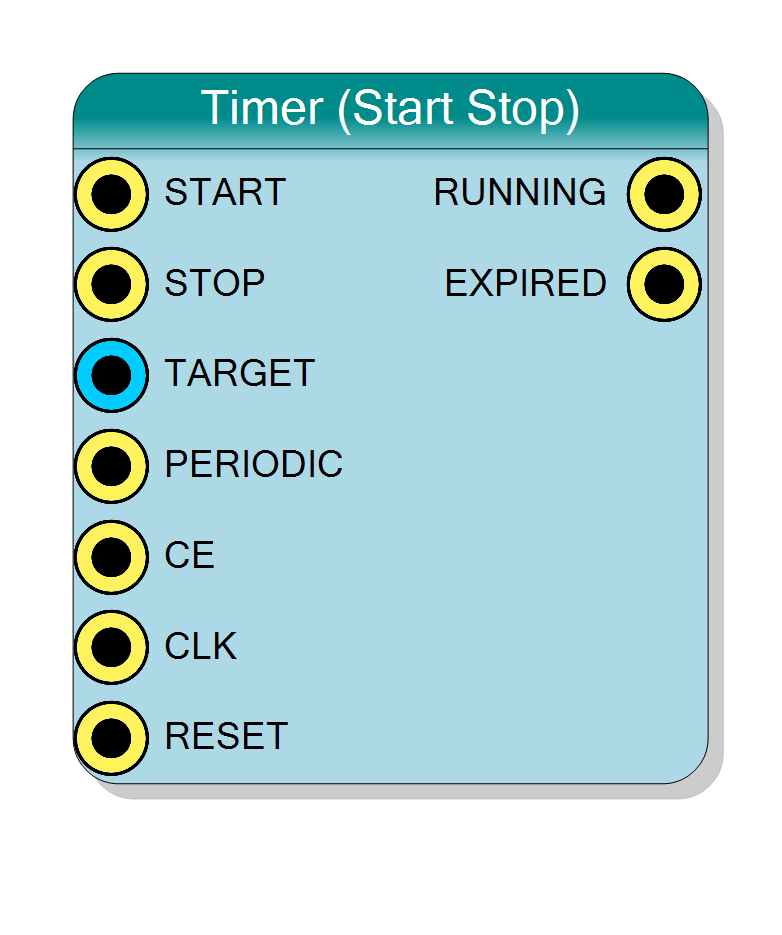
This block implements a programmable countdown timer with START/STOP control, combining features of both the enable-based timer and start/stop chronometer. It counts clock cycles and generates EXPIRED pulses when a target is reached.
Key features:
- Programmable timeout via TARGET input
- Edge-triggered START/STOP control
- Periodic or one-shot operation modes
- Configurable stop behavior in periodic mode
- EXPIRED output pulses when target reached
- Configurable counter width (8-64 bits)
Operation:
- Load target via TARGET input
- Pulse START to begin counting
- Counter increments until TARGET reached
- EXPIRED pulses when COUNT=TARGET
- In periodic mode: auto-restarts or waits for START based on configuration
- STOP pulse can halt timer at any time
Pin Description
Start trigger input (rising edge triggered).
Rising edge initiates countdown:
- Resets counter to 0
- Sets RUNNING=‘1’
- Begins counting toward TARGET
In periodic “Auto restart” mode: Only needed for initial start. In periodic “Wait for start” mode: Needed for each period. In one-shot mode: Needed for each timeout event.
Minimum pulse width: 1 clock cycle.
Stop trigger input (rising edge triggered).
Rising edge halts the timer:
- Clears RUNNING=‘0’
- Resets counter to 0
- Clears EXPIRED
Effective in all modes. New START required to resume.
Minimum pulse width: 1 clock cycle.
Target count input (unsigned integer).
Specifies count value at which EXPIRED is asserted.
Width: Matches Bit Number property
Calculation: TARGET = (Desired_Time × CLK_Freq) - 1
Can be changed dynamically, but keep constant during active counting for predictable behavior.
Range: 0 to 2^BitNumber - 1
Periodic mode control.
- ‘1’ = Periodic mode (behavior set by “Periodic Behaviour” property)
- ‘0’ = One-shot mode
Periodic mode: Timer restarts automatically or on START One-shot mode: Single timeout, requires new START
Can be changed between operations.
Clock enable input (active high).
Global clock enable. When CE=‘0’, counting suspended.
Typically tied to ‘1’ for normal operation.
Default: Connects to ‘1’ if left unconnected.
Clock input.
Counter increments on rising edge when RUNNING=‘1’ and CE=‘1’. START and STOP edges also sampled on rising CLK.
Default: Connects to global clock if left unconnected.
Synchronous reset input (active high).
- ‘1’ = Reset timer: counter to 0, RUNNING=‘0’, EXPIRED=‘0’
- ‘0’ = Normal operation
Master reset independent of START/STOP.
Default: Connects to global reset if left unconnected.
Running status output.
- ‘1’ = Timer actively counting (between START and TARGET/STOP)
- ‘0’ = Timer idle (waiting for START or after timeout/STOP)
Registered output. Transitions:
- ‘0’→‘1’ on START rising edge
- ‘1’→‘0’ on STOP rising edge, TARGET reached, or RESET
Expiration flag output.
Behavior depends on mode:
Periodic + Auto restart:
- Pulses high for one cycle when COUNT=TARGET
- Counter auto-resets, continues counting
Periodic + Wait for start:
- Pulses high for one cycle when COUNT=TARGET
- Counter stops, waits for new START
One-shot:
- Goes high when COUNT=TARGET
- Stays high until new START pulse
Registered output, synchronous to CLK.
Properties
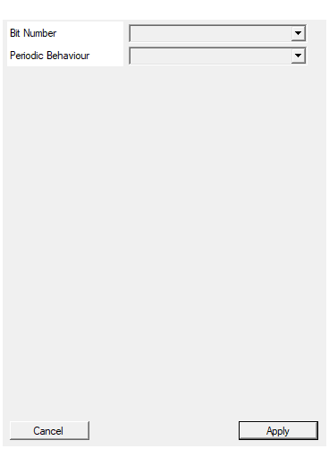
Set the number of bit used in the timer accumulator
Number of bits in the timer counter.
Available values: 8, 16, 24, 32, 40, 48, 56, 64
Determines:
- Maximum TARGET value = 2^BitNumber - 1
- Maximum timeout = (2^BitNumber - 1) / CLK_Frequency
- Width of TARGET input
Choose smallest value meeting timeout requirements.
Default: 32
Options: 8 16 24 32 40 48 56 64
Select if periodic signal is set to 1 if automatic restart or wait for start
Default: 32
Options: Auto restart Wait for start
Controls behavior in periodic mode when TARGET is reached.
“Auto restart” (default):
- Timer automatically restarts from 0
- Continues counting without new START
- Traditional periodic timer
- STOP pulse required to halt
“Wait for start”:
- Timer stops when TARGET reached
- Requires new START pulse for each period
- Software-controlled periodic operation
- Allows inter-period processing
Only applies when PERIODIC=‘1’. Ignored in one-shot mode (PERIODIC=‘0’).
Functional description
The timer implements a state machine with START/STOP control and programmable target comparison:
State machine behavior
IDLE State (RUNNING=‘0’):
- Waiting for START pulse
- Counter holds at 0
- Rising edge on START → COUNTING state
COUNTING State (RUNNING=‘1’):
- Counter increments each clock cycle
- When COUNT=TARGET:
- EXPIRED pulses high
- If PERIODIC=‘1’ and “Auto restart” mode: Counter resets to 0, stay in COUNTING
- If PERIODIC=‘1’ and “Wait for start” mode: Go to IDLE, require new START
- If PERIODIC=‘0’: Go to IDLE, EXPIRED stays high until START
- Rising edge on STOP → IDLE state
Periodic mode behavior
The “Periodic Behaviour” property controls behavior when TARGET is reached:
Auto restart (default):
- Counter automatically resets to 0
- Continues counting without needing new START pulse
- Traditional periodic timer behavior
- STOP pulse required to halt operation
Wait for start:
- Counter stops when TARGET reached
- Requires new START pulse to begin next period
- Useful for externally-triggered periodic events
- Allows software control over each period
Timing formula
$$ \text{Timeout Period (s)} = \frac{\mathrm{TARGET} + 1}{\text{CLK Frequency (Hz)}} $$
Timing diagrams
Periodic mode (Auto restart)
Shows auto-restart behavior:
- START initiates counting
- Counter auto-resets at TARGET
- EXPIRED pulses every 4 cycles
- STOP halts operation
Periodic mode (Wait for start)
Shows wait-for-start behavior:
- Each period requires new START pulse
- Counter stops at TARGET
- EXPIRED pulses when target reached
- Software controls period initiation
One-shot mode
Shows one-shot behavior:
- Single timeout event per START
- EXPIRED pulses once
- New START required for next timeout
Typical use cases
- Triggered timeouts: Generate timeout after external trigger event
- Gated periodic signals: Periodic operation with START/STOP control
- Burst timing: Generate timed bursts of pulses
- Protocol timers: Implement protocol-specific timing with event control
- Software-controlled timing: Flexible timing under CPU control
- Multi-phase timing: Different timing phases controlled by START events
Design considerations
Mode selection guide
Use Periodic + Auto Restart for:
- Continuous periodic operation with stop capability
- Free-running periodic generators
- Regular interrupts or sampling triggers
Use Periodic + Wait for Start for:
- Software-triggered periodic events
- Event-synchronized periodic operation
- Controlled burst generation
Use One-Shot for:
- Single timeout events
- Retriggerable timers
- Watchdog applications
START/STOP signal requirements
- Edge type: Rising edge triggered
- Minimum pulse width: 1 clock cycle
- Simultaneous START/STOP: START takes priority
- Glitch sensitivity: Input should be clean/synchronized
Comparison with other timer types
| Feature | Timer (Enable) | Timer (Start/Stop) | Chrono (Start/Stop) |
|---|---|---|---|
| Control type | Level | Edge | Edge |
| Target countdown | Yes | Yes | No (free-running) |
| EXPIRED output | Yes | Yes | No |
| Use case | Simple timeout | Triggered timeout | Time measurement |