
Derivative [TM]
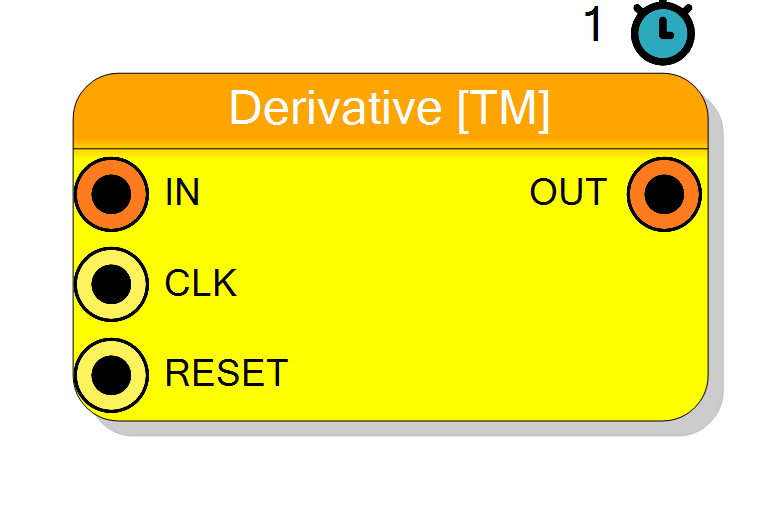
Time-multiplexed discrete-time derivative/differentiator block. Computes first-order backward difference of TM data streams. Supports signed/unsigned input with automatic conversion to signed output (output width = input width + 1 bit). Pipeline latency: 1 cycle.
Introduction
This block computes the discrete-time derivative (first-order backward difference) of a time-multiplexed (TM) input stream, producing a derivative output stream.
On every rising edge of CLK, the component performs:
$$ \mathrm{OUT}(n) = \mathrm{IN}(n) - \mathrm{IN}(n-1), $$
where each TM lane maintains its own previous sample register. The output is always signed (even for unsigned inputs) to correctly represent negative slopes.
Pin Description
Input bits × TM Factor
Can be signed or unsigned (configurable via Input sign property).
(Input bits + 1) × TM Factor
Valid data appear after 1 clock cycle from input.
Properties
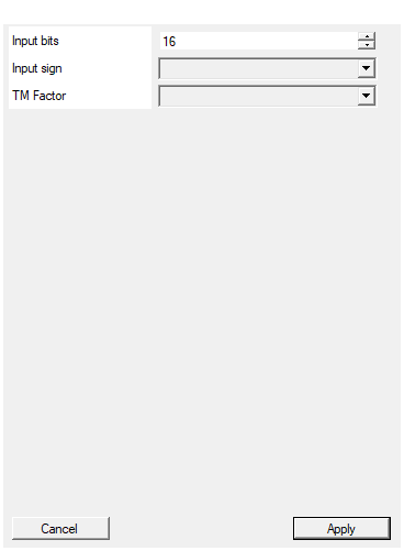
Set the number of bits of the input
Number of bits per input sample ($N_\text{in}$). Range: 4 – 32. Output bit width = $N_\text{in} + 1$ (signed).Default: 16
Range: 4 – 32
Select the sign/unsign of the input
Arithmetic type of the input signal:
UNSIGNED→ Non-negative input valuesSIGNED→ Two’s complement input values
Regardless of input sign, the output is always SIGNED to correctly represent both positive and negative derivatives.
Default: UNSIGNED
Options: UNSIGNED SIGNED
Select the Time Multiplexing factor
Number of time-multiplexed phases (samples per clock). Allowed values: 1, 2, 4, 8, 16, 32.
Each TM lane has an independent delay register and derivative computation. TM Factor = 1 is allowed (single-channel operation).
Default: 4
Options: 1 2 4 8 16 32
Functional description
The component implements a simple first-order differentiator in VHDL, replicated N times (where N = TM Factor) to support time-multiplexed data streams. Each TM lane has an independent delay register.
Operation principle
For each TM phase $i$:
- Store current input sample: $x_i[n]$
- Retrieve previous sample from register: $x_i[n-1]$
- Compute difference: $y_i[n] = x_i[n] - x_i[n-1]$
- Update register with current sample
Output characteristics
- Width: Input bits + 1 (to accommodate full difference range)
- Sign: Always SIGNED (even if input is UNSIGNED)
The extra bit prevents overflow when computing differences like:
- Unsigned: 255 - 0 = 255 (needs 9 bits if input is 8 bits)
- Signed: 127 - (-128) = 255 (needs 9 bits if input is 8 bits)
Initial conditions
On reset, all delay registers are cleared to zero. The first output sample will be: OUT(0) = IN(0) - 0 = IN(0).
Mathematical background
The discrete-time derivative is a highpass FIR filter with transfer function:
$$ H(z) = 1 - z^{-1} $$
In the frequency domain:
$$ H(e^{j\omega}) = 1 - e^{-j\omega} = 2j \sin(\omega/2) e^{-j\omega/2} $$
Characteristics:
- Magnitude: $|H(\omega)| = 2|\sin(\omega/2)|$
- Phase: $\angle H(\omega) = \pi/2 - \omega/2$ (leading phase)
- Gain: 0 at DC ($\omega = 0$), maximum at Nyquist ($\omega = \pi$)
This filter:
- Attenuates low-frequency components (DC blocking)
- Amplifies high-frequency components (emphasizes edges/transients)
- Approximates continuous-time derivative for $\omega \ll \pi$
For small $\omega$:
$$ H(e^{j\omega}) \approx j\omega \quad \Rightarrow \quad y(t) \approx \frac{dx}{dt} $$
Timing
Pipeline latency is fixed at 1 clock cycle:
| Property | Latency (clock cycles) |
|---|---|
| Derivative [TM] | 1 |
Total system delay: T_delay = 1 × T_CLK.
Typical use cases
- Edge detection: Identifying rising/falling edges in detector signals
- Pulse shaping: Generating bipolar pulses from unipolar inputs
- Zero-crossing detection: Preprocessing for timing pickoff circuits
- High-frequency emphasis: Enhancing fast signal components
- Constant Fraction Discriminator (CFD): First stage in timing algorithms
Waveform example
Example with TM Factor = 4, Input = [10, 20, 30, 40, 30, 20, 10, 0].
Note: OUT[0] = IN[0] - 0 = 10, OUT[1] = IN[1] - IN[0] = 20-10 = 10, etc. OUT[4] = IN[4] - IN[3] = 30-40 = -10 (negative slope detected).