
Trigger Derivative Rise Time
Derivative-based digital trigger with BRAM-backed delay line for slow rise-time signals. Computes y = x[n] − x[n−N] where N is runtime-programmable via the RISE_TIME port, enabling clean edge detection on bandwidth-limited preamplifier signals.
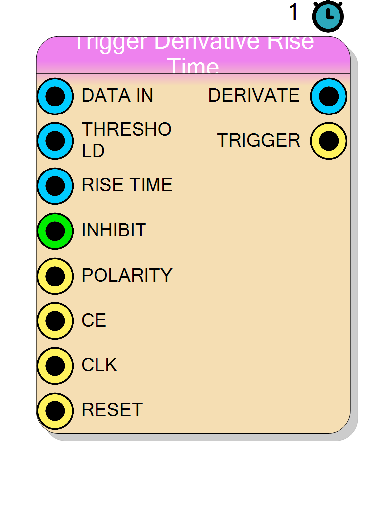
Introduction
The Trigger Derivative Rise Time block implements a derivative-based discriminator designed for signals with slow (finite) rise time, such as charge-sensitive preamplifier outputs or bandwidth-limited detector pulses.
The standard derivative trigger computes x[n] − x[n−1]. On a fast step-like edge
this yields one large spike that easily crosses the threshold. On a slow rise
(spanning many samples), however, consecutive differences are tiny and the derivative
may never exceed the threshold — or it produces a noisy oscillation of many small
spikes instead of a single clean trigger.
This block solves the problem by stretching the subtraction over N samples:
$$ \Delta x[n] ;=; x[n] - x[n-N] $$
Choosing N to match the 10 %–90 % rise time of the signal ensures that the subtraction spans the entire rising edge and captures its full amplitude in one shot, yielding a single clean pulse that crosses the threshold reliably.
N is runtime-programmable via the RISE_TIME input port (no recompilation
required). The delay line is stored in block RAM (BRAM); because BRAM has a
minimum read latency, N is internally clamped to a minimum of 4.
Pin Description
derivative >= threshold.
MemoryDepth − 1 are clamped to MemoryDepth − 1.
TRIGGER pulse (dead-time).
Set to 0 for no inhibition.
Selects derivative polarity.
1– detect positive derivatives (rising edges)0– detect negative derivatives (falling edges) Width = 1 bit.
CE=1; otherwise the internal state is frozen
and outputs keep their last value except TRIGGER, which is forced low.
CLK.
x[n] − x[n−N] (or inverted if POLARITY = 0).
Properties
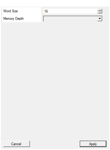
Set the number of bits of the data bus
Bit-width of the input and output data signals. Applies toDATA_IN, THRESHOLD and DERIVATE signals.
Acceptable range: 2 … 64, default 16.
Default: 16
Range: 2 – 64
Maximum rise-time delay (BRAM depth). The RISE_TIME port can select any delay from 4 up to this value.
Depth of the BRAM circular buffer and maximum allowed value for RISE_TIME. Larger values consume more BRAM but allow longer rise-time delays. Available values: 16, 32, 64, 128, 256, 512, 1024, 2048, 4096, default 256.Default: 256
Options: 16 32 64 128 256 512 1024 2048 4096
Usage
Why the standard derivative fails on slow edges
Consider a preamplifier pulse with a 10 %–90 % rise time of ~7 samples.
The standard derivative x[n] − x[n−1] sees only the tiny per-sample increment
during the rise phase. With a 1000-count step spread over 7 samples, each
single-sample difference is ~140 counts — below the threshold needed to reject
noise. Worse, the derivative oscillates producing multiple false triggers.
With N = 7 the subtraction spans the full edge: x[n] − x[n−7] yields a single
~1000-count pulse that cleanly crosses the threshold once.
Transfer function
$$ H(z) = 1 - z^{-N} $$
In the time domain:
$$ \Delta x[n] = x[n] - x[n - N] $$
The POLARITY input selects the sign:
- POLARITY = 1 →
Δx = x[n] − x[n−N](positive / rising edges) - POLARITY = 0 →
Δx = x[n−N] − x[n](negative / falling edges)
Choosing N
N should match the 10 %–90 % rise time of the signal, measured in samples:
$$ N = \left\lfloor \frac{t_{10\text{-}90}}{T_s} \right\rfloor $$
Guidelines:
- N = 4 (minimum): fast-rise signals where BRAM latency is the bottleneck. For truly fast signals (N < 4), use the standard Trigger Derivative instead.
- N = 5–20: typical for charge-sensitive preamplifiers with moderate bandwidth.
- N > 20: very slow preamps (high-capacitance detectors). Ensure
Memory Depthis large enough to accommodate N.
N is runtime-programmable and can be tuned from software without recompiling.
BRAM delay line
The N-sample history is stored in a circular buffer implemented as block RAM.
The Memory Depth property sets the BRAM depth (and therefore the maximum
allowed N). Available depths: 16, 32, 64, 128, 256, 512, 1024, 2048, 4096.
Resource cost scales with Memory Depth × WordSize:
- 256 × 16 bit = 0.5 BRAM18
- 4096 × 16 bit = 4 BRAM18
Pipeline latency
The BRAM read adds one pipeline stage compared to the standard derivative trigger:
| Stage | Description |
|---|---|
| 0 | Write current sample to BRAM; issue read at address wr_ptr − N |
| 1 | BRAM data available; compute derivative |
| 2 | Threshold comparison and edge detection |
Total: ~3 clock cycles from input sample to trigger output.
Trigger logic
The trigger fires on the rising edge of the threshold crossing: the derivative must go from below to above the threshold. After each trigger, new triggers are suppressed for INHIBIT clock cycles (dead-time).
Typical applications
- Edge detection on slow-rise charge-sensitive preamplifier signals
- Trigger for bandwidth-limited detectors (large capacitance, long cables)
- Constant-fraction discriminator pre-stage for slow pulses
- Any application where the standard derivative trigger oscillates or misses edges due to finite rise time