
Counter (Rising Edge)
Synchronous edge counter that counts rising edges on an input signal. Features gated counting control and overflow detection. Operates synchronously to system clock for glitch-free operation. Configurable counter width from 8 to 64 bits.
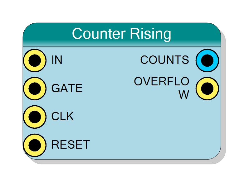
Introduction
This block counts rising edges (0→1 transitions) on the IN input signal. Unlike timers that count clock cycles, edge counters count external events.
Key features:
- Counts rising edges on IN signal
- Synchronous operation (glitch-immune)
- Optional gating control via GATE input
- Overflow detection
- Configurable counter width (8-64 bits)
Operation:
- Detects rising edges on IN input (synchronized to CLK)
- Increments COUNTS by 1 for each rising edge detected
- GATE input enables/disables counting
- OVERFLOW pulses when counter wraps around
$$ \mathrm{COUNTS}(n+1) = \begin{cases} \mathrm{COUNTS}(n) + 1 & \text{if Rising Edge on IN and GATE=‘1’} \ \mathrm{COUNTS}(n) & \text{otherwise} \end{cases} $$
Pin Description
Input signal to count.
Rising edges (0→1 transitions) on this signal are counted.
Synchronization: Signal is sampled on CLK rising edge. Glitches shorter than one clock period are ignored.
Frequency limit: Maximum countable frequency is CLK_Frequency / 2 (Nyquist limit). For reliable operation, keep IN frequency below CLK_Frequency / 4.
Edge detection: Rising edge detected when IN was ‘0’ in previous cycle and is ‘1’ in current cycle.
Gate control input (active high).
- ‘1’ = Counting enabled (rising edges counted)
- ‘0’ = Counting disabled (rising edges ignored, count holds value)
Useful for:
- Time-windowed counting
- Conditional event counting
- Burst detection
Default: Connects to ‘1’ if left unconnected (always enabled).
Clock input.
Functions:
- Samples IN signal on rising edge
- Clocks edge detection logic
- Updates counter value
Counter increments when rising edge detected and GATE=‘1’.
Default: Connects to global clock if left unconnected.
Synchronous reset input (active high).
- ‘1’ = Reset counter to 0, clear overflow flag
- ‘0’ = Normal operation
Resets counter regardless of IN, GATE states.
Default: Connects to global reset if left unconnected.
Current count output (unsigned integer).
Contains the number of rising edges detected since last reset.
Width: Configured by Bit Number property
Behavior:
- Increments by 1 for each rising edge on IN (when GATE=‘1’)
- Wraps to 0 after reaching maximum (2^BitNumber - 1)
- Holds value when GATE=‘0’
- Resets to 0 on RESET=‘0’
Update timing: Count increments 2 clock cycles after physical rising edge on IN (synchronization + edge detection).
Registered output, stable and glitch-free.
Overflow flag output (single-cycle pulse).
Pulses high for one clock cycle when counter wraps from maximum value (2^BitNumber - 1) to 0.
Use cases:
- Overflow detection for error handling
- Extended precision counting (use as carry to higher-order counter)
- Event notification when count limit reached
- Frequency division (periodic pulse every 2^N edges)
Registered output, synchronous to CLK.
Properties
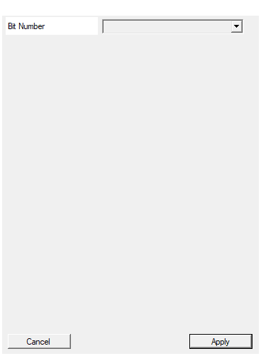
Set the number of bit used in the counter accumulator
Number of bits in the counter.
Available values: 8, 16, 24, 32, 40, 48, 56, 64
Determines:
- Maximum count = 2^BitNumber - 1
- Width of COUNTS output
- Counter overflow period = 2^BitNumber edges
Choose based on maximum expected edge count between resets.
Examples:
- 8-bit: Counts 0-255, overflows at 256
- 32-bit: Counts 0-4,294,967,295, overflows at 4,294,967,296
Default: 32
Options: 8 16 24 32 40 48 56 64
Functional description
The counter implements synchronous edge detection by registering the IN signal and comparing consecutive values:
Edge detection mechanism
$$ \text{Rising Edge} = \text{IN}(n) \land \overline{\text{IN}(n-1)} $$
Where:
- IN(n) = Current value of IN signal
- IN(n-1) = Previous value of IN signal (from last clock)
- ∧ = AND operation
- ‾ = NOT operation
A rising edge is detected when:
- Previous cycle: IN=‘0’
- Current cycle: IN=‘1’
Synchronous operation
All edge detection is synchronized to the system clock (CLK):
- IN signal sampled on each CLK rising edge
- Provides immunity to glitches shorter than one clock period
- Introduces 1-2 cycle latency for edge detection
- Maximum countable frequency: CLK_Frequency / 2 (Nyquist limit)
Gated counting
The GATE input provides enable/disable control:
- GATE=‘1’: Rising edges are counted
- GATE=‘0’: Rising edges are ignored, counter holds value
- GATE is sampled synchronously (same as IN)
Overflow behavior
When counter reaches maximum value (2^N - 1):
- Counter wraps to 0 on next rising edge
- OVERFLOW output pulses high for one clock cycle
- Counting continues from 0
Timing diagram
The diagram shows:
- IN signal synchronized to CLK (IN_sync)
- Rising edges detected (Edge_det)
- Counter increments on each rising edge
- One clock cycle latency from IN edge to COUNT increment
Typical use cases
- Event counting: Count occurrences of external events
- Pulse counting: Count pulses from sensors or detectors
- Frequency division verification: Verify divider output pulse count
- Trigger counting: Count number of trigger events
- Digital tachometer: Count encoder pulses for speed measurement
- Activity monitoring: Count state machine transitions or packet events
- Interrupt counting: Track number of interrupt occurrences
Design considerations
Input signal requirements
Frequency limits:
- Maximum input frequency: CLK_Frequency / 2
- For 100 MHz clock: Max input frequency = 50 MHz
- For reliable counting: Input frequency < CLK_Frequency / 4
Pulse width:
- Minimum high time: 1 clock period
- Minimum low time: 1 clock period
- Minimum period: 2 clock periods
Signal quality:
- Synchronous edge detection filters glitches < 1 clock period
- For noisy signals, consider external debouncing
- For async signals: Already synchronized internally
Choosing bit width
Select based on maximum expected count:
| Bit Width | Max Count | Use Case |
|---|---|---|
| 8 bits | 255 | Small event counts, frequent reset |
| 16 bits | 65,535 | Moderate event counts |
| 24 bits | 16,777,215 | Large event counts |
| 32 bits | 4,294,967,295 | Very large counts, rare overflow |
| 64 bits | 2^64 - 1 | Unlimited counting applications |
Edge detection latency
- Latency: 2 clock cycles from physical edge to counter increment
- 1 cycle: Input synchronization
- 1 cycle: Edge detection and counter update
- For time-critical applications, account for this latency
- Latency is constant and predictable
Using GATE effectively
- Measurement windows: Enable counting only during specific periods
- Conditional counting: Count edges only when conditions met
- Burst counting: Count edges in bursts, ignore between bursts
- GATE can be used to implement “count N edges” functionality
Synchronous vs Asynchronous counters
This is a synchronous counter:
- Pros: Glitch immune, predictable timing, integrates with synchronous designs
- Cons: Max frequency = CLK_Freq/2, uses more resources than async
For faster counting with same clock, see Counter Rising Async.