
Petiroc Slow Control
Slow-control programmer for one PETIROC-2A on the DT5550W. It shifts the 640-bit chip configuration (and the 200-bit probe/monitor register) into the ASIC over its serial SLOAD/CLK/MOSI interface, either automatically after boot, or from the design through pins, or at runtime from the host through 21 memory-mapped registers and the generated SciSDK functions.
Introduction
Principle of Operation
Everything that makes a PETIROC-2A behave the way an experiment needs - the per-channel 6-bit and 4-bit trimming DACs, the discriminator thresholds, the preamplifier gains, the channel masks, the TDC ramp settings - lives in one long configuration shift register inside the chip. On the PETIROC-2A that register is 640 bits long. A second, shorter register (200 bits) selects which internal node is routed to the analogue probe outputs.
This block is the writer for both. It implements the chip’s slow-control protocol as a plain bit-banged shift:
RESETB ──┐ ┌────────
└──────────────────────────────────────────────────────┘
CLK ──────┐ ┌──┐ ┌──┐ ┌──┐ ┌──┐ ┌──────────────────
└──┘ └──┘ └──┘ └── … ──────────┘ └──┘
MOSI ═══╡b639╞═╡b638╞═╡b637╞═ … ═══════════════╡ b0 ╞═══════════════
SLOAD ──────────────────────────────────────────────────┐ ┌──────────
└──┘
SELECT ═════ '1' = main configuration / '0' = probe register ══════
The bit period is set by the VHDL generic Halfbit, which the component
never overrides, so it always keeps its entity default of 10000 clock
cycles per half bit. One bit therefore takes 20 000 clock cycles, and a full
640-bit load takes roughly
$$ 640 \times 2 \times 10000 + 24 \times 10000 \approx 1.3 \times 10^{7}\ \text{clock cycles} $$
(≈ 80 ms on the DT5550W’s 160 MHz global clock). This is intentional: the
PETIROC slow-control interface is slow and asynchronous by design, and the
configuration is loaded once at start of run, not per event. BUSY is high
for the whole time.
Three ways to program the chip
| Source | Trigger | Where the bits come from |
|---|---|---|
| Automatic at boot | StartupProgram = True |
the ASIC Configuration property, frozen into the bitstream as a VHDL generic |
| From the design | falling edge on START_CFG |
the ASIC_CONFIGURATION pin, captured while LOAD_CFG is high |
| From the host | SciSDK PETIROC_<name>_CONFIG() |
20 × 32-bit registers REG_CFG0…19, latched by a write to START_REG_CFG |
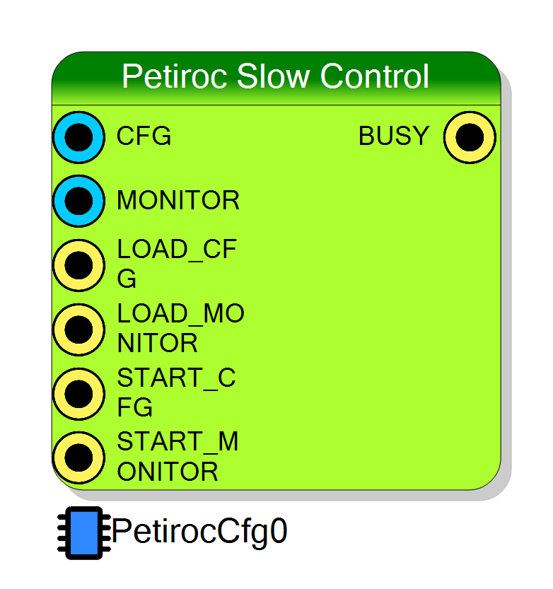
Pin Description
LOAD_CFG is high. Bit 639 is shifted out first. Leave
open if you configure only from the property or from the host.
LOAD_MONITOR is high,
then shifted out with SELECT low. The symbol says 195 bits, the
generated pad and the entity port are 200 - see the alert in the
description.
ASIC_CONFIGURATION – level, not a pulse. The
shadow register reverts to the compile-time default on every clock this
pin is low, so it must be held high through the START_CFG falling edge.
ASIC_MONITOR_CONFIGURATION – same level semantics
as LOAD_CFG.
1 → 0). The shift takes ≈ 1.3 × 10⁷ clock cycles; BUSY is high
throughout and further edges during that time are ignored (the state
machine is not in idle).
SELECT
driven low, 200 bits instead of 640.
Properties
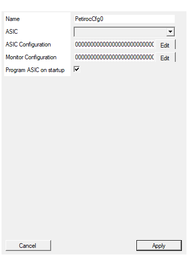
Set the name of the endpoint
Name of the memory-mapped endpoint this block creates. It becomes the
prefix of every generated register and SciSDK symbol:
SCI_REG_<EndpointName>_REG_CFG0, PETIROC_<EndpointName>_CONFIG(),
PETIROC_<EndpointName>_CONFIG_MON(). It also names the wrapper signals
REG_<EndpointName>_REG_CFG<k>_WR. Must be unique across the project and
a valid C identifier, because it is pasted into the generated header.
Changing it rebuilds the symbol.
Default: PetirocCfg0
Default: PetirocCfg0
Select the ASIC to be connected to the Endpoint
Selects which of the four PETIROC-2A chips is written. The letter is
pasted into the five board signals the block drives:
PETIROC_<ASIC>_CLK_s, PETIROC_<ASIC>_MOSI_s,
PETIROC_<ASIC>_SLOAD_s, PETIROC_<ASIC>_RESETB_s,
PETIROC_<ASIC>_SELECT_s.
Hidden (isVisible = False): the board plug-in sets it when the block is
placed.
Default: A
Default: A
Options: A B C D
Set the ASIC configuration programmed on startup.
The 640-character ASCII bit string (‘0’/‘1’) programmed into the chip at
startup and used whenever no other source has overridden the shadow
register. It is bound to the VHDL generic CfgDefault, so character 0 is
configuration bit 639 and is shifted out first.
Click the property to open the plug-in’s PETIROC configuration window, which generates the string from named fields (thresholds, per-channel DACs, masks, gains) rather than raw bits. Typing it by hand is possible but error-prone, and remember the bit-order alert in the description before reusing a string that came from the SciSDK path.
Default: the 640-bit factory string shipped with the component
Default: 0000000000000000000000000000000000000001100000001100000001100000001100000001100000001100000001100000001100000001100000001100000001100000001100000001100000001100000001100000001100000001100000001100000001100000001100000001100000001100000001100000001100000001100000001100000001100000001100000001100000001100000001100000001100010000000000000000000000000000000000000000010000010000010000010000010000010000010000010000010000010000010000010000010000010000010000010000010000010000010000010000010000010000010000010000010000010000010000010000010000010000010000011101001011000111110100110011110100000111111111011111111010011111111001111111111011001011
Set the ASIC Monitor Outputs configuration. Configuration will start only upon monitor cfg command
The 200-character ASCII bit string for the probe/monitor register, bound
to the VHDL generic CfgMonitorDefault. It selects which internal node is
routed to the analogue probe outputs. It is not programmed at startup:
the chip only receives it after a START_MONITOR falling edge or a
START_REG_CFG = 2 command (“Configuration will start only upon monitor
cfg command”). Has its own editor dialog.
Default: 199 zeros followed by a single ‘1’
Default: 00000000000000000000000000000000000000000000000000000000000000000000000000000000000000000000000000000000000000000000000000000000000000000000000000000000000000000000000000000000000000000000000000000001
If true, the ASIC will be programmed after board boodstap with default configuration
When true, the generic DoStartupSetup is "1" and the block programs
the chip once, automatically, after a power-on delay of 2²⁴ ≈ 16.8 million
clock cycles (≈ 105 ms at 160 MHz), using DefaultConfiguration. A
startUpProg_done latch makes it a one-shot: it does not repeat, and a
later configuration from the pins or the host is not undone.
Set it false if the host always configures the chip explicitly at start of run and you do not want the ASIC to be written with a stale bitstream in between.
Default: True
Default: True
⚙️ Detailed Operation
The programming state machine
On a start request (from any of the three sources) the machine runs:
| State | Action | Dwell |
|---|---|---|
x"0" |
idle, SELECT = 1, BUSY = 0. On start: load the bit counter (639 or 199), latch the bitstream, drop RESETB and SLOAD |
— |
| 2 × Halfbit | ||
x"1" |
raise RESETB |
10 × Halfbit |
x"2" |
CLK low, put bit ASIC_BITSTREAM(count) on MOSI |
1 × Halfbit |
x"3" |
CLK high |
1 × Halfbit |
x"4" |
CLK low, decrement the counter; loop to x"2" until it reaches 0 |
— |
x"5" |
SLOAD high (transfer shift register → configuration latches) |
4 × Halfbit |
x"6" |
SLOAD low, back to idle |
4 × Halfbit |
The bit counter starts at the top index and counts down, so
ASIC_BITSTREAM(639) is shifted out first and bit 0 last.
Programming the probe register is the same sequence with SELECT driven low,
a bit counter of 199, and only bits 199…0 of the shift register loaded.
Startup programming
When StartupProgram is true the generic DoStartupSetup is "1" and a
24-bit counter, initialised to 0xFFFFFF, counts down after reset. When it
reaches zero the machine programs the chip once with the ASIC Configuration
property (a startUpProg_done latch makes sure it happens exactly once). The
delay is ≈ 16.8 million clock cycles (≈ 105 ms at 160 MHz) and exists to let
the board’s power rails and clocks settle before the ASIC is written.
Host path: the register file
CompileMMC declares the endpoint with 21 write registers:
| Register | Meaning |
|---|---|
REG_CFG0 … REG_CFG19 |
20 × 32 bits = 640 bits of configuration |
START_REG_CFG |
command register, only bits 1:0 are decoded |
START_REG_CFG is edge-decoded on its low two bits:
| Value written | Effect |
|---|---|
01 |
copy REG_CFG0…19 into the 640-bit configuration and start a main programming cycle |
10 |
copy REG_CFG0…5 and the low byte of REG_CFG6 into the 200-bit probe register and start a monitor programming cycle |
00 |
idle (the value the SDK writes before and after each command) |
REG_CFG<k> maps to configuration bits 32k+31 … 32k, so REG_CFG0 bit 0 is
the last bit shifted out and REG_CFG19 bit 31 is the first.
SciSDK
CompileSDK emits, for an endpoint called e.g. PetirocCfg0:
SCILIB int PETIROC_PetirocCfg0_CONFIG (char *incfg, NI_HANDLE *handle);
SCILIB int PETIROC_PetirocCfg0_CONFIG_MON(char *incfg, NI_HANDLE *handle);
Both take the configuration as an ASCII string of ‘0’/‘1’ characters -
640 characters for CONFIG, 200 for CONFIG_MON. Both start with a length
check that is the only error path in the function:
if (strlen(incfg) != 640) return -1; /* CONFIG */
if (strlen(incfg) != 200) return -1; /* CONFIG_MON */
The body packs the characters into the 20 registers, writes them, then pulses
the command register 0 → 1 → 0 (or 0 → 2 → 0 for the monitor). The
equivalent Python functions are generated as well.
The compiler prints, per endpoint:
Generating memory mapped component: <EndpointName>
SDK starting code generation
SDK[C] adding function: PETIROC_<EndpointName>_CONFIG
SDK[C] adding function: PETIROC_<EndpointName>_CONFIG_MON
SDK[C] adding register definitions
and, if the endpoint never got an address assigned, the fatal
SDK address undefined for <EndpointName>
Design path: the pins
ASIC_CONFIGURATION / ASIC_MONITOR_CONFIGURATION are the parallel buses,
LOAD_CFG / LOAD_MONITOR capture them into the shadow registers, and
START_CFG / START_MONITOR launch the shift.
The integrated bitstream editor
DefaultConfiguration and MonitorConfiguration are TextDialog
properties: clicking them opens the plug-in’s own PETIROC configuration
window (Petiroc2UI.PetirocFWClass.OpenConfigWindowAndGetString /
OpenConfigWindowMonitorAndGetString), which builds the bit string from named
fields instead of requiring you to type 640 characters. Use it - hand-editing
the string is the main source of mis-configured chips. (The dialog is not
available in the .NET Core build of the plug-in, where the property falls back
to plain text.)
Board signals driven
PETIROC_<ASIC>_CLK_s, _MOSI_s, _SLOAD_s, _RESETB_s, _SELECT_s for
the selected chip. Place one instance per ASIC; two instances on the same
letter would double-drive those five signals.
Resources & Timing
-
Latency: Main configuration: 640 bits × 2 × Halfbit + 20 × Halfbit of prologue/epilogue ≈ 1.3 × 10⁷ clock cycles (≈ 80 ms at 160 MHz). Probe register: 200 bits, ≈ 4.2 × 10⁶ clock cycles (≈ 26 ms).
-
Throughput: One programming cycle at a time; BUSY is high throughout and new start requests are ignored while the state machine is out of idle.
Halfbitis a generic of the VHDL entity with default 10000 and the component never passes a value for it, so the bit rate is fixed at clk/20000 and cannot be changed from the property grid.- Startup programming waits 0xFFFFFF clock cycles after reset before it fires.