
Multi MUX
N-channel multiplexer for a whole SET of signals at once, each with its own width, direction and register option. One SEL value routes all the signals of the set together: forward signals (IN->OUT) carry the selected channel to a common output, reverse signals (OUT->IN, e.g. back-pressure) carry a common input back to the selected channel only, with a configurable idle value on the unselected channels.
Introduction
The Multi MUX block multiplexes a group of signals with a single selector. Where the plain Multiplexer routes one data bus, the Multi MUX routes an entire interface - data, valid strobes and back-pressure - as one unit.
The signal set is defined in a dedicated Multi MUX Designer window (double-click the block): for each signal you choose
- Name - the pin base name (e.g.
WORD,DV,BUSY); - Width in bits;
- Direction:
- IN -> OUT (“forward”): the block gets
NAME_0..NAME_{N-1}inputs and oneNAMEoutput with the selected channel; - OUT <- IN (“reverse”): the block gets one
NAMEinput andNAME_0..NAME_{N-1}outputs; only the selected channel receives the input;
- IN -> OUT (“forward”): the block gets
- Registered - re-time the routed value on CLK (one clock latency);
- Unselected value - ‘0’ or ‘1’, driven on the unselected outputs of a reverse signal (and on forward outputs when SEL is out of range).
The number of channels N (2..64) is set in the same window. SEL is ceil(log2(N)) bits. A CLK pin appears automatically when at least one signal is registered.
Pin Description
Properties
Signal set of the Multi MUX, produced by the Multi MUX Designer
Hidden property holding the whole signal-set configuration; edit it exclusively through the Multi MUX Designer (double-click the block).Default: 4;1|WORD,32,F,0,0|DV,1,F,0,0|BUSY,1,R,0,1
Usage
Typical use case
Four arbiters write into a single FIFO; software enables exactly one of them via SEL:
Signals: WORD 32 bit IN->OUT, DV 1 bit IN->OUT, BUSY 1 bit OUT<-IN (idle '1')
Channels: 4
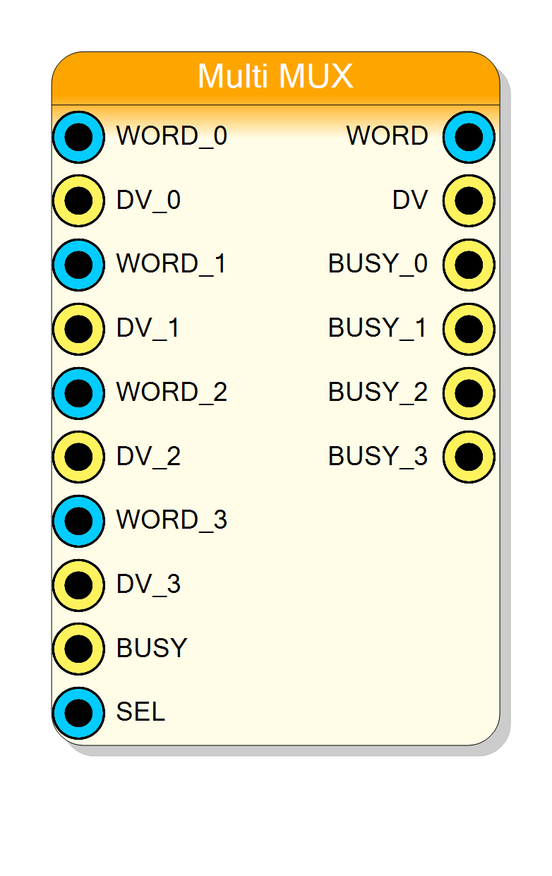
Inputs : WORD_0 DV_0 WORD_1 DV_1 WORD_2 DV_2 WORD_3 DV_3 BUSY SEL
Outputs: WORD DV BUSY_0 BUSY_1 BUSY_2 BUSY_3
With SEL = 0 the FIFO sees WORD_0/DV_0 and the arbiter 0 sees the FIFO’s BUSY; arbiters 1..3 see BUSY_x = ‘1’ (the configured idle), so they hold their traffic while deselected. Choosing idle ‘0’ instead would let the deselected arbiters free-run.
Routing rules
- All signals switch together on the same SEL value.
- Combinational signals (Registered unchecked) propagate within the same clock cycle, with pure combinational delay.
- Registered signals are re-timed: one clock of latency through the block. Mixing registered and combinational signals in the same set is allowed - mind the one-cycle skew between them.
- If SEL is out of range (N not a power of two), forward outputs drive their idle value.
Generated hardware
The block emits a per-instance specialised VHDL entity (no generics: the port list itself follows the configuration). Routing is a simple when/else selector per signal plus an optional output register - no RAM, no primitives.
Resources & Timing
-
Latency: 0 clocks (combinational signals) or 1 clock (registered signals)
-
Throughput: combinational routing, no stall
Pure LUT routing plus one register layer per registered signal. Resource usage scales with the total signal width times N.