
Baseline Restorer
Real-time baseline estimation block for single-sample input signals. Computes a moving average of input samples to estimate the signal baseline, with automatic hold during pulse events to prevent bias from signal excursions.
Introduction
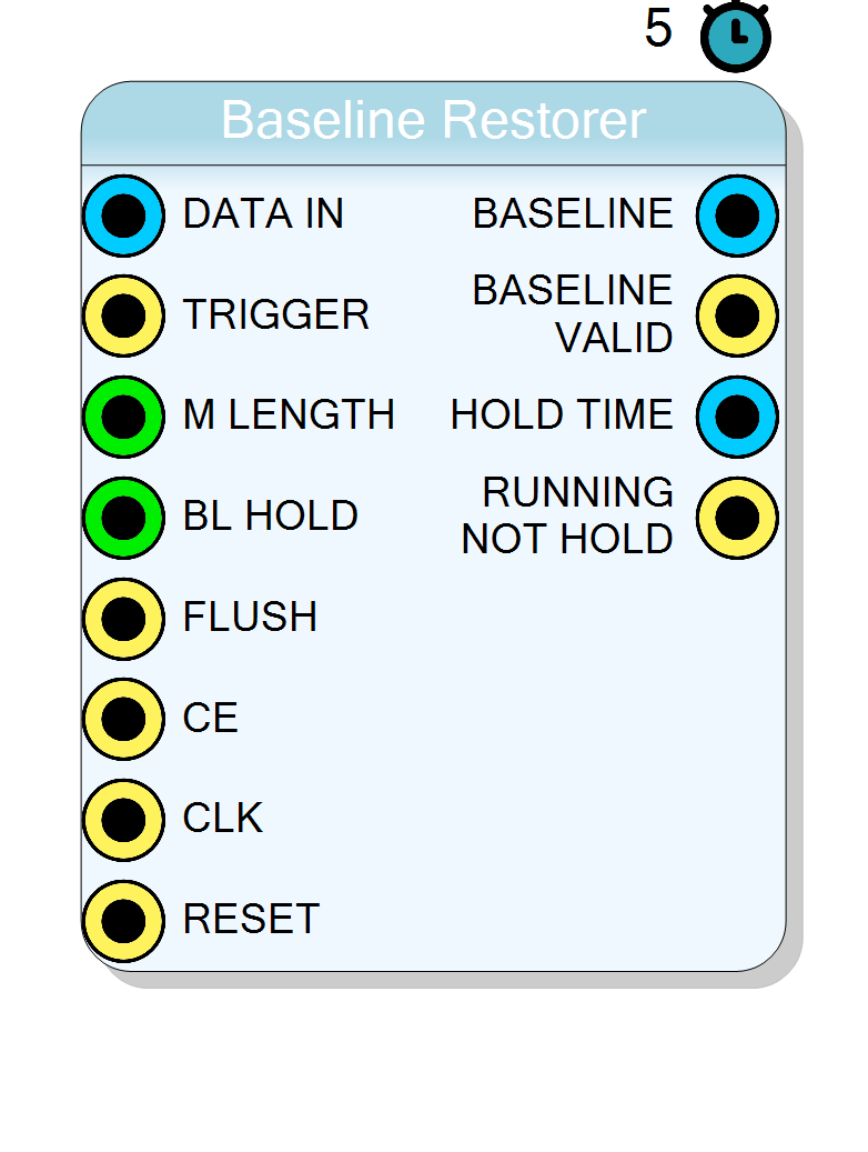
The Baseline Restorer block performs real-time baseline estimation on a single-sample input signal. Its main function is to compute the average (baseline) of the incoming signal samples over a defined integration period, and to pause this calculation when an event (trigger) is detected.
This ensures that transient signal excursions (pulses) do not bias the baseline estimation, which is critical for accurate pulse-height analysis in spectroscopy applications.
This is the non-time-multiplexed version of the baseline restorer, processing one sample per clock cycle.
Pin Description
BL_HOLD.
2^M_LENGTH.
Minimum value: 3 (8 samples), Maximum: limited by MaxLength property.
Example: M_LENGTH=9 gives 512 samples.
Properties
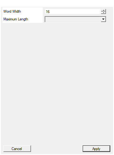
Width of the input data in bits
Bit-width of the input and output data signals. Applies toDATA_IN and BASELINE signals.
Acceptable range: 4 … 32, default 16.
Default: 16
Range: 4 – 32
Maximum number of samples for the moving average
Maximum number of samples that can be used for baseline calculation. Determines the maximum allowed value for M_LENGTH. Available values: 1024, 2048, 4096, 8192, default 1024.Default: 1024
Options: 1024 2048 4096 8192
Usage
Functional Overview
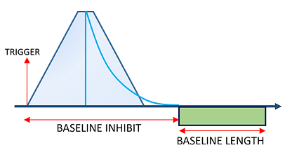
The figure shows:
- TRIGGER: The trigger signal that initiates the hold period
- BASELINE INHIBIT: The period during which baseline calculation is suspended (to exclude the pulse)
- BASELINE LENGTH: The integration window for computing the average
How It Works
The input signal arrives through the DATA_IN port as a single sample per clock cycle. When the trigger signal (TRIGGER) goes HIGH, the baseline computation is suspended to prevent the pulse from biasing the baseline estimate.
Baseline Window Size
The baseline is computed over a number of samples defined by the M_LENGTH input. The window size is calculated using the formula:
$$ \text{Baseline Length} = 2^{\text{M_LENGTH}} $$
| M_LENGTH value | Number of samples |
|---|---|
| 5 | 32 |
| 6 | 64 |
| 7 | 128 |
| 8 | 256 |
| 9 | 512 |
| 10 | 1024 |
| 11 | 2048 |
Hold Duration
When a trigger occurs, the computation is suspended for a duration defined by the BL_HOLD input. This value specifies the number of clock cycles during which the baseline will be inhibited.
The actual hold duration in time units is:
$$ \text{Hold Time} = \text{BL_HOLD} \times T_{clk} $$
where $T_{clk}$ is the clock period.
Example: If the clock period is 10 ns and BL_HOLD = 100, the hold duration will be: $$100 \times 10,\text{ns} = 1,\mu\text{s}$$
Timing Diagram
The diagram shows:
- When
TRIGGERgoes high, theHOLDsignal activates - During the hold period,
BASELINEoutput remains frozen (samples are excluded) - After the hold period ends, baseline integration resumes and a new
BASELINEvalue is computed
Output Signals
- BASELINE: The computed baseline value (moving average of input samples)
- BASELINE_VALID: Asserts HIGH when the first valid baseline has been computed after integration
- RUNNING_NOT_HOLD: HIGH when the block is actively integrating (not in hold state)
- HOLD_TIME: Counter showing the number of clock cycles during which the block is in hold
Typical Applications
- Pulse-height analysis (PHA) in gamma-ray spectroscopy
- Baseline correction for Multi-Channel Analyzers (MCA)
- Signal conditioning for scintillator/SiPM detectors
- Real-time DC offset removal