
Peak Detector
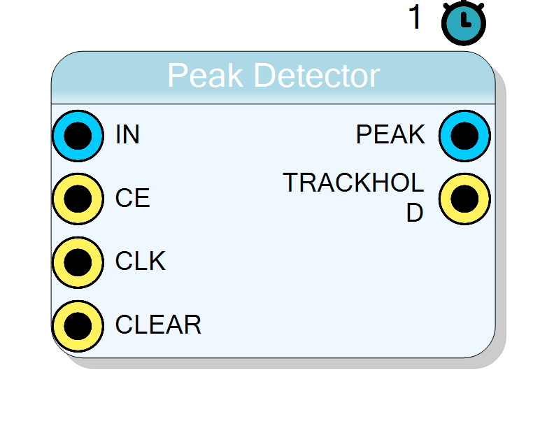
Single-channel digital peak detector that continuously tracks the maximum amplitude of the input sample stream. The current peak value is exported on DATA_OUT while TRACKHOLD indicates whether the circuit is in the track (0) or hold (1) phase. A synchronous active-high RESET clears the stored peak. One clock-cycle latency is introduced between the qualifying input sample and the corresponding output update.
Introduction
The PK_STRETCHERp core implements a real-time peak detector
acquisition chains. At every rising edge of CLK, the
module compares the current DATA_IN sample with the peak accumulated since
the last reset:
$$ \mathrm{PEAK}(n) = \max{0 \leq k \leq n}{,\text{DATAIN}(k),} $$
If the new sample exceeds the stored value, the peak is updated (track),
otherwise the previous maximum is preserved (hold). The flag TRACKHOLD
is asserted to 1 during the hold phase and cleared during tracking,
allowing external logic to gate ADC read-outs
graph LR
DIN[DATA_IN] -- compare --> C{DATA_IN > PEAK}
C -- yes --> UPD[Update PEAK]
C -- no --> HOLD[Hold PEAK]
UPD --> DOUT[DATA_OUT]
HOLD --> DOUT
DOUT --> OUT[System]
Pin Description
Size is
WordWidth bits (default = 16).Sample is considered valid only when
CE=1.
When asserted, the core performs the comparison
DATA_IN > PEAK.If de-asserted the internal registers keep their value and
TRACKHOLD remains unchanged.
All internal registers, including the synchronous RESET, are sampled on this edge.
Sets
PEAK, DATA_OUT, and TRACKHOLD to zero within one
clock cycle.
Same width as
DATA_IN.
•
0 = tracking (current sample updated the peak)•
1 = holding (current sample ≤ stored peak)
Properties
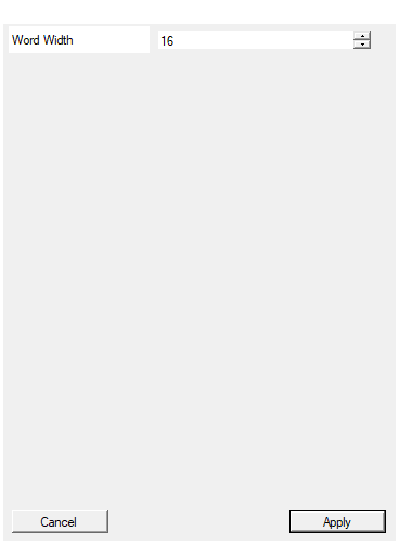
Width of the input data in bits
Bit-width of DATA_IN and DATA_OUT buses
• Range : 4 – 32 bits
• Default: 16 bits
Impact on resources is linear. Comparator and register bank size
scale with WordWidth; timing is virtually unaffected for small
variations (< 32 bits).
Default: 16
Range: 4 – 32
Functional Overview
A digital peak detector is the discrete-time counterpart of an analog peak-and-hold circuit. For each clock cycle n the core computes
$$ \text{PEAK}(n) = \begin{cases} 0 & \text{if RESET}(n)=1 \ \max(\text{PEAK}(n-1),\ \text{DATAIN}(n)) & \text{if CE}(n)=1 \ \text{PEAK}(n-1) & \text{otherwise} \end{cases} $$
The output bus DATA_OUT carries the value $\text{PEAK}(n-1)$, hence the
detected maximum is available one clock period after the decisive
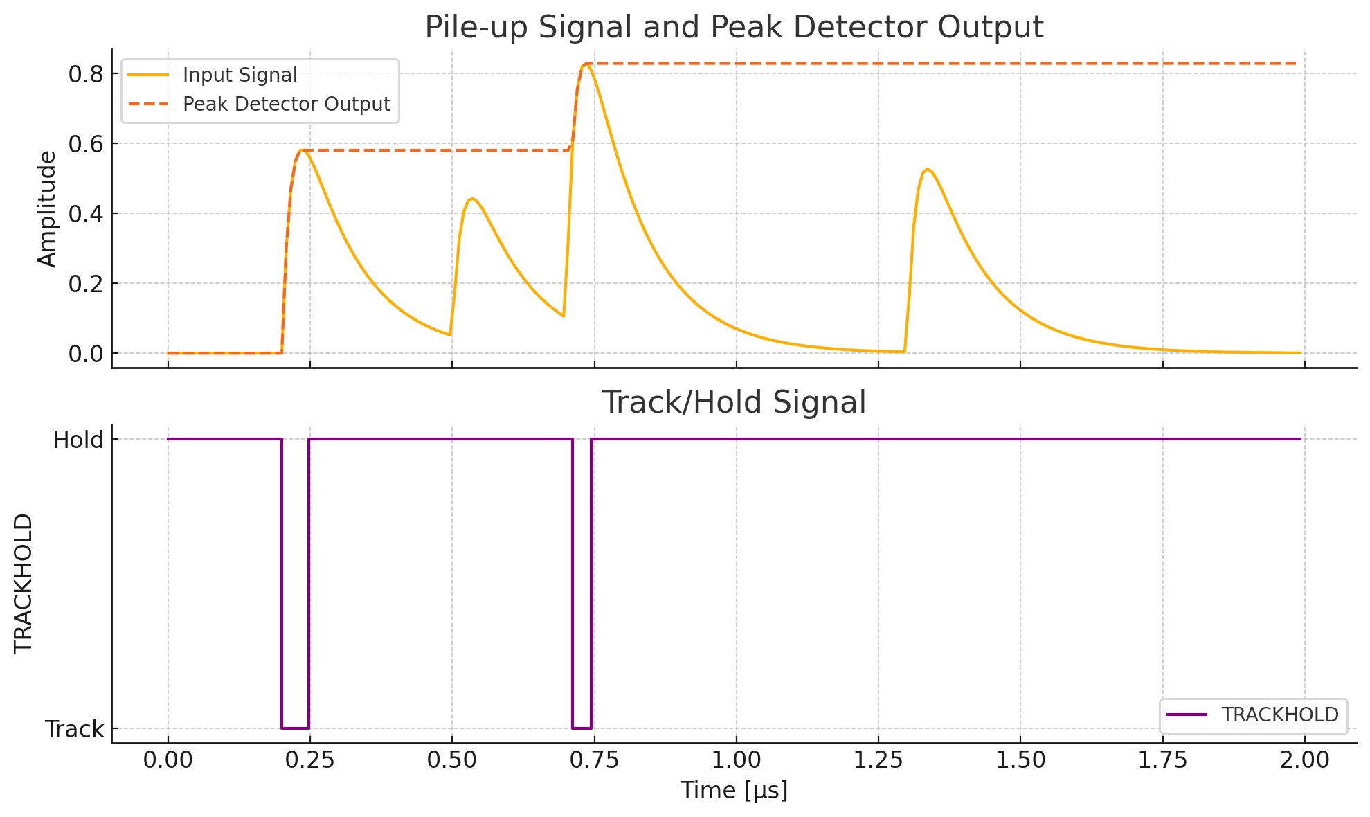
comparison. Figure 1 illustrates the behaviour.
Mathematical and Physical Background
In nuclear spectroscopy and particle-physics DAQ chains the amplitude of a shaped pulse is proportional to the deposited energy:
$$E \propto V_{\text{peak}} = \max_t{,v_{\text{shaper}}(t),}$$
While analog peak stretcher ICs are sensitive to temperature drift and component tolerances, a digital implementation guarantees repeatability and immunity to offsets. The core can be combined with a digital Constant Fraction Discriminator (CFD) or a multi-channel analyzer (MCA).
Timing
- Latency: 1
CLKrising edge from the cycle whereCE=1andDATA_IN > PEAKto the update ofDATA_OUT. - Reset timing: Synchronous, sampled on the rising edge of
CLK. WhenRESET=1, bothDATA_OUTand the internal peak register are cleared in the same cycle.
Typical Use-Cases
- Energy measurement in HPGe or SiPM based gamma detectors
- Pulse-height analysis for radiation monitoring
- Envelope detection in communication receivers
- Maximum finder in control loops (e.g. duty-cycle optimisation)