
Counter Falling Edge (Async)
Asynchronous edge counter that counts falling edges on an input signal. Counter increments directly on input falling edges without clock synchronization, enabling counting of frequencies higher than system clock. Features gated counting control and overflow detection. Configurable counter width from 8 to 64 bits.
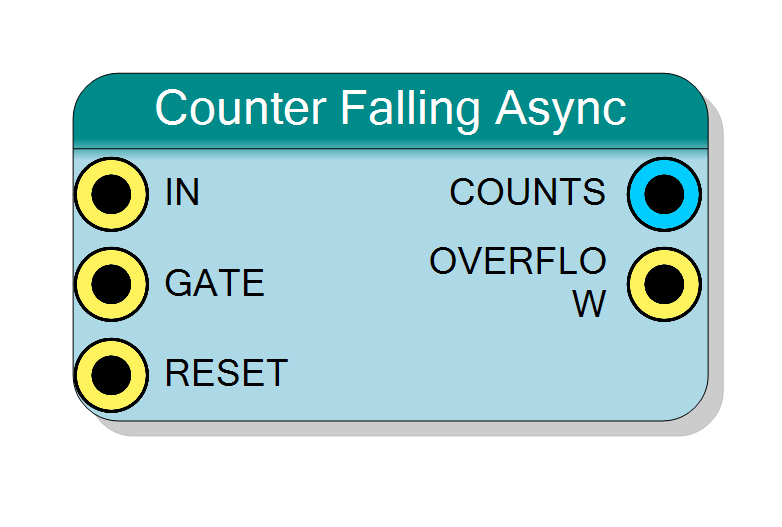
Introduction
This block counts falling edges asynchronously - falling edges on the IN signal directly increment the counter without synchronization to system clock. Enables counting frequencies higher than the system clock frequency.
Key features:
- Counts falling edges (1→0) asynchronously
- Can count signals faster than system clock
- Optional gating control via GATE input
- Overflow detection
- Configurable counter width (8-64 bits)
Identical to Rising Edge Async counter except:
- Detects falling edges (1→0) instead of rising (0→1)
- All other characteristics the same
$$ \mathrm{COUNTS}(n+1) = \mathrm{COUNTS}(n) + 1 \quad \text{on each Falling Edge of IN} $$
Pin Description
Input signal to count (asynchronous clock).
Falling edges (1→0 transitions) directly increment counter without synchronization.
Frequency capability:
- Practical limit: ~500 MHz (FPGA dependent)
- No system clock frequency restriction
Signal requirements:
- Clean falling edges (no glitches)
- Minimum low pulse width: ~2-3 ns
Edge type: Falling edge (1→0) increments counter
Warning: Operates in different clock domain than system clock.
Gate control input (active high).
- ‘1’ = Counting enabled
- ‘0’ = Counting disabled
Should be static or carefully synchronized to avoid metastability.
Default: Connects to ‘1’ if left unconnected.
Asynchronous reset input (active high).
- ‘1’ = Reset counter to 0 immediately
- ‘0’ = Normal operation
Takes effect immediately (not synchronized).
Default: Connects to global reset if left unconnected.
Current count output (unsigned integer).
Number of falling edges detected since last reset.
Width: Configured by Bit Number property
CRITICAL: This output is asynchronous (IN clock domain). Must be synchronized to system clock for safe reading.
Safe reading methods:
- Double-synchronize to system clock
- Gray code conversion
- Static read only
- Accept metastability risk (if appropriate)
Increments asynchronously on IN falling edges.
Overflow flag output (pulse).
Pulses when counter wraps from maximum to 0.
Timing: Asynchronous, occurs on IN edge causing wrap.
Should be synchronized if used in synchronous logic.
Properties
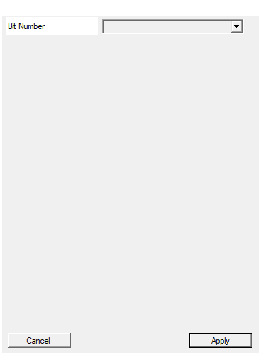
Set the number of bit used in the counter accumulator
Number of bits in the counter.
Available values: 8, 16, 24, 32, 40, 48, 56, 64
Determines maximum count and COUNTS output width.
For very high frequencies (>200 MHz), narrower counters have shorter ripple delays.
Default: 32
Options: 8 16 24 32 40 48 56 64
Functional description
The asynchronous counter uses falling edges of IN signal to directly clock the counter, without system clock synchronization.
Edge polarity
- Rising Edge Async: Counts 0→1 transitions
- Falling Edge Async: Counts 1→0 transitions (this component)
- Operation: Otherwise identical to rising edge version
Typical applications for falling edge
Choose Falling Edge Async when:
- Signal of interest is active-high (count when pulses end)
- Sensor or source outputs falling-edge markers
- Need to complement rising edge counting
- Measuring falling edge timing
Asynchronous operation characteristics
Same as Rising Edge Async counter:
- No system clock frequency limit
- Can count up to ~500 MHz (FPGA limit)
- Metastability risk when reading
- Zero latency counting
- Clock domain crossing required for reads
Reading and metastability
Same considerations as Rising Edge Async:
- COUNTS is in IN clock domain (not system clock)
- Requires synchronization for safe reading
- Double-synchronizer or gray code recommended
- See Rising Edge Async documentation for details
Typical use cases
- High-frequency falling edge counting: Count fast falling edges
- Pulse completion counting: Count when high-speed pulses complete
- Return-to-idle counting: Count falling edges marking event completion
- Complementary to rising edge: Use both for duty cycle measurement
- Active-high event counting: Count ends of active-high events
Design considerations
Same as Rising Edge Async counter. Key points:
When to use
- Input frequency > System clock / 2
- Falling edges mark significant events
- Maximum frequency capability needed
- Can tolerate metastability (with proper handling)
Metastability mitigation
Required when reading COUNTS in system clock domain:
- Double synchronizer (2 flip-flops)
- Gray code conversion
- Handshake protocol
- Static read (when IN stable)
Input requirements
- Clean falling edges (no bouncing)
- Minimum low pulse width: ~2-3 ns
- Maximum frequency: ~500 MHz (FPGA dependent)