
DSP - BLOCK AUTOCORRELATION
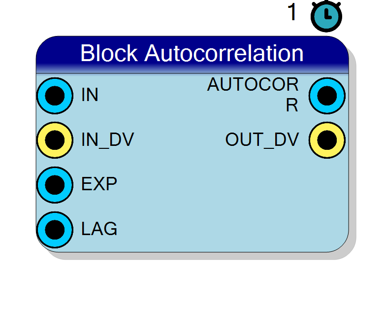
The autocorrelation COEFFICIENT rho(k) of a block of N consecutive samples, at a lag k that is a RUNTIME INPUT PIN. This is the standard BIASED sample autocorrelation WITH THE MEAN REMOVED - which is the point: a raw autocorrelation on a pedestalled signal correlates with itself at every lag simply because it is positive. rho is dimensionless, gain independent and bounded to [-1,+1]; rho(0) is exactly 1 and is NOT special cased, which makes it a free self test on live hardware. BECAUSE THE LAG IS A PIN a design can SWEEP it - one block per lag - and reconstruct the whole correlogram without rebuilding the IP: peaks are periodicity, a fast decay is white noise, a slow decay is a low-pass or drifting signal. It is latched per block exactly like EXP and clamped to the Max Lag property, which sizes the ONLY memory in the block: a Max Lag-deep delay line. NO second pass and NO sample buffer - an exact integer identity collapses the centred products into raw power sums. Three serial multiply passes and one division: L = IN_SW + EXP + SEW + CNUMW + 10, around 170 clocks at the default formats, so budget a long block. LAG >= N forces the output to 0 and that one IS a real guard. IN_DV is the only qualifier and there is deliberately no CE pin. Optional BUSY / INTEGRATING / SAMPLE_COUNT status outputs.
Introduction
The Block Autocorrelation block chops the input stream into consecutive blocks of N samples and, at the end of each block, publishes the autocorrelation coefficient of that block at a lag k:
$$ \rho(k) = \frac{\sum_{i=k}^{N-1} (x_i - \mu)(x_{i-k} - \mu)} {\sum_{i=0}^{N-1} (x_i - \mu)^2}, \qquad \mu = \frac{1}{N}\sum_{i=0}^{N-1} x_i $$
This is the standard biased sample autocorrelation coefficient: $\rho(0) = 1$ exactly, $|\rho(k)| \le 1$, and it is dimensionless and gain independent - amplify the signal and $\rho$ does not move.
THE MEAN IS REMOVED, and that is the point
An autocorrelation taken on the raw samples is dominated by the DC level: a signal sitting on a pedestal correlates with itself at every lag simply because it is positive, and the answer is a slab near 1 that tells you nothing. Subtracting $\mu$ - the mean of the same block - makes $\rho(k)$ answer the question actually being asked: is there structure at this lag?
You do not have to remove the baseline upstream, and you must not: the block removes the mean of the block it is reporting on, which is the right mean even if the baseline drifts from block to block.
THE LAG IS A PIN, not a property
LAG is a 6 bit input, so a design can sweep it - one block per lag - and
reconstruct the whole correlogram $\rho(1), \rho(2), \ldots$ without
rebuilding the IP. That is what makes this block a measurement instrument
rather than a fixed filter:
- drive
LAGfrom a counter and you get a correlogram at one lag per block; - drive it from a register interface and a CPU can hunt for a period;
- hold it fixed and you get a single-lag monitor for free.
LAG is latched on the first sample of each block, exactly like EXP, so
a block is never accumulated at one lag and reported at another. It is
clamped to the Max Lag property, which is what sizes the delay line.
N is a runtime input too
You drive the exponent on the EXP pin and the block size is
$N = 2^{\mathrm{EXP}}$:
| EXP | N | EXP | N |
|---|---|---|---|
| 8 | 256 | 14 | 16384 |
| 9 | 512 | 16 | 65536 |
| 10 | 1024 | 20 | 1048576 |
The table starts at 256 on purpose: this block has a serial tail of well over a hundred clocks. See “The serial tail”.
How to read the answer
Sweep LAG and look at the shape:
| what you see | what it means |
|---|---|
| peaks at $k = P, 2P, 3P \ldots$ | periodicity with period $P$ samples - a tone, a rotating machine, a mains ripple, a pulse train |
| fast decay to ~0 within a few lags | white / uncorrelated noise - there is no structure to find |
| slow decay over many lags | a low-pass or drifting signal: successive samples are not independent |
| $\rho$ negative at $k = 1$ | sample-to-sample alternation - high-frequency content near Nyquist, or a differentiated signal |
| $\rho(1)$ near 1, staying near 1 | you are oversampling: consecutive samples carry almost the same information |
A correlogram is also the cheapest period estimator that does not need an FFT: find the first $k > 0$ at which $\rho$ peaks.
What it is FOR
- period / pitch detection on a channel with no threshold to speak of;
- noise characterisation: is my noise white, or is it filtered? $\rho(1)$ alone answers that;
- oversampling and effective bandwidth checks on a digitiser chain;
- pile-up / after-pulse hunting in pulse processing - an after-pulse at a fixed delay shows up as a bump at that lag;
- vibration monitoring, where a periodic component appearing in the correlogram is a bearing or a gear mesh.
Cost
Per clock, while accumulating: two multipliers ($x^2$ for the power sum and $x \cdot x_{i-k}$ for the lagged product), four accumulators and the only memory in the block - a Max Lag-deep delay line, which is a shift register (an SRL on Xilinx), not a RAM.
There is no second pass and no sample buffer: the block never re-reads the samples. An exact integer identity (below) collapses the centred products into raw power sums plus one small correction, so all the block has to remember is the last Max Lag samples. Compare that with Block Mean Abs Deviation, which really does have to store the whole block and therefore runs at half rate.
In the tail: one reused shift-add stage driven through three multiply passes, and one restoring divider. No DSP in the tail.
When to use this instead of Block Statistics
The all-in-one Block Statistics block is not deprecated, but it does not compute an autocorrelation: it has no delay line and no lagged-product accumulator, so there is no counterpart to this statistic over there. The usual rule still applies to everything else you may want from the same data:
- you want several statistics of the SAME block - mean and RMS and min/max of the same N samples - use Block Statistics. They share one accumulator and one serial tail, so the second and third statistic are nearly free.
- you want exactly one number - use a per-operator block. Then you synthesise only that number, and nothing else reaches the synthesiser.
A Block Variance placed next to this one will duplicate the $S_1$ / $S_2$ accumulators this block already keeps internally. That is two adders’ worth of duplication and it is not a reason to avoid either block.
Pin Description
IN_DV is high. Do not remove the
baseline upstream - the block removes the mean of the very block it is
reporting on, which is the right one.
IN_DV
cannot displace the lagged sample either. The serial tail keeps running
regardless. Unconnected defaults to '1'. (There is deliberately no CE
pin - to stall the block, gate this.)
The lag k of the autocorrelation, runtime programmable: 6 bits
unsigned, accepted range 0 .. Max Lag, larger values clamped to Max
Lag. Sampled on the first accepted sample of a block and held for that
whole block, exactly like EXP, so a block is never accumulated at one
lag and reported at another; a change takes effect on the next block that
STARTS - which on a gapless stream is before the previous block’s
OUT_DV, so plan the pairing (see “Sweeping the lag”). LAG = 0 gives
$\rho = 1$ exactly and is not special cased, which makes it a free self
test. LAG $\ge$ N means the block and its shifted copy do not
overlap, and the output is forced to 0. Unconnected defaults to 1
- the shortest meaningful lag.
LAG $\ge$ N.
Updated on the OUT_DV clock and on no other; it holds the previous
block’s result until then.
AUTOCORR is updated on this
clock and on no other. BUSY is still high here and falls on the next
clock. A block whose result was dropped for being too short produces no
pulse at all - that is the only symptom. Note that on a gapless stream
this pulse arrives after the next block has already latched its LAG.
OUT_DV pulse,
and it falls on the clock after. On a continuous stream it simply stays
high. Present on the symbol only when Enable BUSY = YES.
BUSY high with INTEGRATING low is exactly the
three-products-then-divide tail. On a continuous stream it dips for one
clock per block boundary, which makes it a free block marker - and the
right edge to count when sequencing a lag sweep. Present on the symbol
only when Enable INTEGRATING = YES.
How many samples have been accumulated so far in the current block: 1 after the first, N after the N-th. It is NOT cleared at the end of a block
- it HOLDS the final count through the tail and past
OUT_DV, until the first sample of the next block takes it back to 1, it reads N atOUT_DVonly when the input STOPS for the whole tail. On a CONTINUOUS stream the next block has already started by then, soOUT_DVshows how far into it the input has got, not N - the clock that always reads N is the oneINTEGRATINGfalls on. OnlyRESETclears it to 0. Fixed 32 bits. Present on the symbol only when Enable SAMPLE_COUNT = YES.
Properties
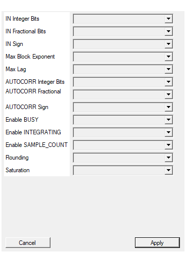
Number of INTEGER bits of the input sample (the sign, when present, uses one of them).
Integer bits of the input sample (the sign, when present, uses one of them). 1..64. Default 16. Each input bit costs four clocks of serial tail and one bit of delay-line width per stage.Default: 16
Options: 1 2 3 4 5 6 7 8 9 10 11 12 13 14 15 16 17 18 19 20 21 22 23 24 25 26 27 28 29 30 31 32 33 34 35 36 37 38 39 40 41 42 43 44 45 46 47 48 49 50 51 52 53 54 55 56 57 58 59 60 61 62 63 64
Number of FRACTIONAL bits of the input sample, i.e. the bits to the right of the binary point. Total width = integer + fractional bits, and must not exceed 64.
Fractional bits of the input sample. 0..64. Total input width must be 2..64 bits. Default 0. They do not change the value of $\rho$ - it is a ratio of two quantities with the same units, so the scalings cancel - so they buy nothing here except tail length, at the same four clocks each as integer bits.Default: 0
Options: 0 1 2 3 4 5 6 7 8 9 10 11 12 13 14 15 16 17 18 19 20 21 22 23 24 25 26 27 28 29 30 31 32 33 34 35 36 37 38 39 40 41 42 43 44 45 46 47 48 49 50 51 52 53 54 55 56 57 58 59 60 61 62 63 64
Select whether the input sample is signed (two’s complement) or unsigned.
SIGNED (two’s complement) or UNSIGNED input. Default SIGNED. An UNSIGNED input costs one extra bit internally, because a sample has to be promoted to signed before it can be accumulated - and that bit costs four clocks of tail like any other. Note that an unsigned input is exactly the pedestalled case the mean removal exists for.Default: SIGNED
Options: UNSIGNED SIGNED
Largest block-size exponent the accumulators are sized for: the block can be up to 2^MaxBlockExponent samples long. The EXP input is clamped to this value at run time. Raising it widens the internal accumulators, and ON THE BLOCKS WHOSE SERIAL ENGINES ARE SIZED FROM THOSE ACCUMULATORS (Coefficient of Variation, SNR, Skewness, Kurtosis, Correlation, Autocorrelation, Linear Regression) it also LENGTHENS THE SERIAL TAIL – even when the runtime EXP is small. Keep it at the largest block you actually use. The default of 20 covers blocks of up to 1048576 samples.
Largest block-size exponent the accumulators are sized for: the block can be up to $2^{\text{MaxBlockExponent}}$ samples long, and theEXP input
is clamped to this value at run time. Raising it widens the internal power
sums and lengthens the serial tail by three clocks per unit, because
it widens the numerator and therefore the divider. Keep it at the largest
block you actually use. It must also be at least the minimum usable
exponent of the configuration - with a 16 bit signed input at Q2.14 that
means 7 or more, and anything lower is refused by the property page.
1..31, default 20, i.e. blocks of up to 1048576 samples out of the
box.
Default: 20
Options: 1 2 3 4 5 6 7 8 9 10 11 12 13 14 15 16 17 18 19 20 21 22 23 24 25 26 27 28 29 30 31
Deepest lag the block can be asked for. It sizes the delay line (MaxLag sample registers, a shift register on Xilinx) and the runtime LAG input is CLAMPED to it. 63 is the ceiling because the LAG pin is 6 bits wide.
Deepest lag the block can be asked for. It sizes the delay line - Max Lag sample registers, a shift register (SRL) on Xilinx - and the runtimeLAG input is clamped to it. 63 is the ceiling because the
LAG pin is 6 bits wide. 1..63, default 16. This is the cheap knob:
it costs registers only and adds no clocks at all to the serial tail
(the $P_2 \cdot k$ pass is always six steps whatever the lag is), so ask
for the deepest lag you intend to sweep to.
Default: 16
Options: 1 2 3 4 5 6 7 8 9 10 11 12 13 14 15 16 17 18 19 20 21 22 23 24 25 26 27 28 29 30 31 32 33 34 35 36 37 38 39 40 41 42 43 44 45 46 47 48 49 50 51 52 53 54 55 56 57 58 59 60 61 62 63
Number of INTEGER bits of the AUTOCORR output (the sign, when present, uses one of them).
Integer bits of the AUTOCORR output. 1..64, default 2, and 2 is the right answer: $|\rho| \le 1$, so two integer bits cover the value and its sign with room to spare (Q2.14 holds up to 1.99994 and $+1.0$ is 16384). Raising it only throws resolution away. It costs no clocks.Default: 2
Options: 1 2 3 4 5 6 7 8 9 10 11 12 13 14 15 16 17 18 19 20 21 22 23 24 25 26 27 28 29 30 31 32 33 34 35 36 37 38 39 40 41 42 43 44 45 46 47 48 49 50 51 52 53 54 55 56 57 58 59 60 61 62 63 64
Number of FRACTIONAL bits of the AUTOCORR output, i.e. the bits to the right of the binary point. Total width = integer + fractional bits, and must not exceed 64.
Fractional bits of the AUTOCORR output. 0..64, total width 2..64 bits, default 14 - steps of $1/16384 \approx 6\times10^{-5}$. This is where all the resolution goes, since the integer part is fixed by $|\rho| \le 1$. Each fractional bit adds one clock to the serial divider.Default: 14
Options: 0 1 2 3 4 5 6 7 8 9 10 11 12 13 14 15 16 17 18 19 20 21 22 23 24 25 26 27 28 29 30 31 32 33 34 35 36 37 38 39 40 41 42 43 44 45 46 47 48 49 50 51 52 53 54 55 56 57 58 59 60 61 62 63 64
Select whether the AUTOCORR output is signed (two’s complement) or unsigned.
SIGNED or UNSIGNED AUTOCORR output. Default SIGNED, and it should stay that way: a negative $\rho$ - alternating samples, or the trough of a periodic correlogram - is real information, and an UNSIGNED format clamps every negative lag to 0, flattening exactly the features a correlogram is read for. Choose UNSIGNED only when you know the signal cannot anti-correlate at the lags you sweep.Default: SIGNED
Options: UNSIGNED SIGNED
YES: the BUSY (high from the first sample of a block until its result is out – it COVERS THE SERIAL TAIL, and its last high clock IS the OUT_DV pulse) pin is present. NO: the pin AND all of its logic are removed BEFORE synthesis, so nothing is paid for it.
YES: theBUSY pin exists. It is high from the first sample of a block
until its result is out, tail included, and its last high clock is the
OUT_DV pulse. NO: the pin and its register are removed before synthesis.
Default NO.
Default: NO
Options: NO YES
YES: the INTEGRATING (high only while the block is ACCUMULATING; it drops as soon as the N-th sample has been taken and the tail starts, so BUSY-and-not-INTEGRATING means ‘computing’) pin is present. NO: the pin AND all of its logic are removed BEFORE synthesis, so nothing is paid for it.
YES: theINTEGRATING pin exists. It is high only while the block is
accumulating, so BUSY high with INTEGRATING low means “the samples are
all in, the products and the divider are running”. Its one-clock dip per
block boundary is also the natural edge to step a lag sweep on. NO: the
pin and its register are removed. Default NO.
Default: NO
Options: NO YES
YES: the SAMPLE_COUNT (32 bit, how many samples have been accumulated so far in the current block: 1 after the first, N after the N-th. It is NOT cleared at the block end – it holds N until the NEXT block’s first accepted sample takes it back to 1. On a CONTINUOUS stream that happens DURING the serial tail, so at OUT_DV it reads how far into the next block the input has already got, NOT N. To capture the length of the block being presented, latch SAMPLE_COUNT on the clock INTEGRATING falls – that one always reads N) pin is present. NO: the pin AND all of its logic are removed BEFORE synthesis, so nothing is paid for it.
YES: theSAMPLE_COUNT pin exists - a fixed 32 bit count of the samples
accumulated so far in the current block, holding the final count through
the tail and past OUT_DV. On this block it is the cheapest way to
confirm at run time that EXP really is large enough. NO: the pin and its
counter are removed. Default NO.
Default: NO
Options: NO YES
ROUND: round to nearest when a result has to be requantised into a coarser output format. TRUNCATE: drop the bits (cheaper, adds a negative bias).
ROUND: round to nearest when a result has to be requantised into a coarser output format. TRUNCATE: drop the bits. On this block it has no effect on the value: the serial quotient already comes out at AUTOCORR Fractional Bits, so the final requantisation has nothing to shift and nothing to round. The magnitude of the quotient is always floored by the restoring divider, and the golden model floors it the same way - which is why the regression tolerance is zero. Default ROUND.Default: ROUND
Options: TRUNCATE ROUND
YES: clip to the largest representable value of each output format (symmetric for signed formats). NO: wrap around.
YES: clip to the largest representable value of the AUTOCORR format (symmetric bounds for signed formats). NO: wrap around. With the default Q2.14 it never fires, because $|\rho| \le 1$ and 1.0 is well inside the format. It only becomes reachable if you choose a format too narrow for the $[-1,+1]$ range. Default YES.Default: YES
Options: NO YES
The exact-integer identity: why there is no second pass
Expanding the centred products and clearing the denominators turns the definition into arithmetic on raw power sums, which can all be accumulated in one streaming pass. With
$$ S_1 = \sum_{i} x_i, \qquad S_2 = \sum_{i} x_i^2, \qquad S_{xy} = \sum_{i \ge k} x_i , x_{i-k}, \qquad P_2 = S_1^2 $$
and $S_{ed}$ the sum of the two end runs - the $k$ samples the shifted copy loses off the front and the $k$ it loses off the back,
$$ S_{ed} = \sum_{i < k} x_i ; + \sum_{i \ge N-k} x_i $$
the two lagged windows have sums $S_1 - \text{head}$ and $S_1 - \text{tail}$, so everything collapses to
$$ \mathrm{num} = N^2 S_{xy} - N P_2 + N S_1 S_{ed} - k P_2, \qquad \mathrm{den} = N,(N S_2 - P_2), \qquad \rho = \frac{\mathrm{num}}{\mathrm{den}} $$
Every $N\cdot$ and $N^2\cdot$ is a shift (N is a power of two). ONE end-run accumulator replaces the two separate window sums. The only term that is not a shift of a product is $k P_2$ - and $k \le 63$, so that multiply is six serial steps, not $\mathrm{IN_SW} + \mathrm{EXP}$ of them.
Note $\mathrm{den} = N \times$ the variance numerator that Block Variance computes, which is why a constant block falls out correctly: $\mathrm{den}$ is 0, $\mathrm{num}$ is 0 as well (every centred product vanishes), and the zero-denominator path reports 0.
Accuracy
The magnitude of the quotient is floored to AUTOCORR Fractional Bits and the sign is applied afterwards. Everything before that division is exact integer arithmetic - no accumulated rounding, no truncated intermediate.
The host regression (tb/block-ops/run_tb.ps1) therefore demands tolerance
ZERO against a Python golden (tb/block-ops/gen_golden.py) that evaluates
the centred definition in exact rational arithmetic and floors it the same
way - not “within 1 LSB”, not “within a few counts”. Any deviation at all
fails the build.
The two corner cases
LAG = 0 gives rho = 1 EXACTLY, and it is NOT special cased
With $k = 0$ the delay line is bypassed - $x_{i-0}$ is the sample itself - and the identity degenerates: the numerator becomes the denominator, term for term, and the quotient is exactly $1.0$, i.e. 16384 in the default Q2.14.
There is no if (lag == 0) anywhere in the core. The arithmetic reaches
the right answer on its own, which makes LAG = 0 a free self test on live
hardware: drive it and the output must read exactly $2^{\mathrm{ACF_{fract}}}$.
If it does not, something upstream - the input format, the IN_DV timing, the
block framing - is wrong, and you have found out without a simulator.
LAG >= N forces the output to 0, and that one IS a real guard
If the lag is at least as long as the block, the block and its shifted copy do not overlap at all: there is nothing to correlate. The identity above is only valid for $0 \le k \le N$, so this case is detected and the output is forced to 0 - it is a genuine guard, not a formality.
In a correctly sized design you cannot reach it: LAG is 6 bits and
clamped to Max Lag (63 at the very most), while the minimum usable EXP
for this block’s tail is already 7 or 8, i.e. $N \ge 128$. It only becomes
reachable if you drive EXP below the minimum the compiler printed - in
which case most of your results are being dropped anyway (see below). The
regression exercises it exactly that way, on purpose.
Sweeping the lag
LAG is sampled on the first accepted sample of a block and held for that
whole block, so a change takes effect on the next block that STARTS. On a
gapless stream the next block starts on the very next clock after the previous
one ended - which is before the previous block’s OUT_DV, because the
tail is long. Two consequences worth planning for:
- do not update
LAGfromOUT_DVand expect the very next result to use it. By the timeOUT_DVfor block n pulses, block n+1 has already latched its lag; your new value lands on block n+2. Keep a small shadow register chain of the lag values you drove, and pair eachOUT_DVwith the right one. - or make it unambiguous by dropping
IN_DVbetween blocks: with the stream gated off during the tail there is only ever one block in flight,OUT_DVarrives before the next block starts, and “updateLAGonOUT_DV” does exactly what it looks like. You pay one block period of throughput per point of the correlogram.
Either way the value is always self-consistent: a block is never accumulated at one lag and reported at another.
Accumulation and IN_DV
IN_DV is the only qualifier. It says “this clock carries a sample”: the
sample is squared into $S_2$, added to $S_1$, multiplied by the delayed sample
into $S_{xy}$ when the shifted copy still overlaps, added to $S_{ed}$ when it
falls in an end run, shifted into the delay line, and counted towards N -
exactly on the clocks where IN_DV is high. Clocks with IN_DV low are
ignored completely, including by the delay line: whatever sits on IN
during them cannot corrupt the block and cannot displace the lagged sample.
The serial tail keeps running regardless, which is what you want.
(The delay line is deliberately not cleared at a block boundary. It never needs to be: $S_{xy}$ only takes a pair whose partner is inside the same block.)
Unconnected, IN_DV ties to '1', EXP ties to 10 (N = 1024) and LAG
ties to 1 - the shortest meaningful lag, so an unwired block reports the
one-sample correlation rather than the trivial $\rho(0) = 1$.
There is deliberately no CE pin. On the all-in-one Block Statistics block an earlier revision had one, and it did not survive synthesis: with nothing but internal state gated by it, Vitis could reason the frozen path away and delete the port from the generated entity while SciCompiler’s wrapper still wired it, which failed a real Vivado build with [VRFC 10-718] formal port <ce> does not exist in entity. The whole per-operator family was built without one. To stall this block, gate its
IN_DV- a block that only accumulates onIN_DVhas no need to be frozen, and there is no reason to stall the tail.
When EXP changes
EXP is clamped to Max Block Exponent and then latched on the first
accepted sample of a block, and held for that whole block - and so is the
“does the lag still overlap?” decision that depends on it. A change therefore
takes effect on the NEXT block: a block in progress always finishes
against the N it was started with, and a block is never emitted against a
different N than the one it was accumulated with. Remember that EXP also
has to satisfy $2^{\mathrm{EXP}} \ge L$ at run time, every time.
Timing: the serial tail
The latency contract
OUT_DV pulses for one clock when the tail COMPLETES, L clocks after the
clock on which the N-th sample of the block was accepted - not when that
sample arrives. AUTOCORR is updated on that same clock and on no other. The
state walk is
IDLE -(go)-> MUL2 x (IN_SW+EXP) -> MULE x SEW -> MULK x 6
-> VAR -> CLD -> DIV x CNUMW -> FIN -> IDLE
- the three multiply passes being $|S_1|\cdot|S_1|$, $|S_1|\cdot|S_{ed}|$ and
$P_2 \cdot k$ - with
OUT_DVregistered, so
$$ L = (\mathrm{IN_SW} + \mathrm{EXP}) + \mathrm{SEW} + 6 + 1 + 1 + \mathrm{CNUMW} + 1 + 1 $$
with the widths fixed at compile time by your formats:
$$ \mathrm{SEW} = \mathrm{IN_SW} + 7 $$
$$ \mathrm{MW} = \max\bigl(2,\mathrm{IN_SW} + 3,\mathrm{MaxBlockExponent},; 2,\mathrm{IN_SW} + 2,\mathrm{MaxBlockExponent} + 7 \bigr) + 2 $$
$$ \mathrm{CNUMW} = \max\bigl(\mathrm{MW} + \mathrm{ACF_{fract}},; \mathrm{AUTOCORR\ width} + 2\bigr) $$
where $\mathrm{IN_SW}$ is the signed working width of a sample: the input width, +1 if the input is UNSIGNED.
What each knob costs, in clocks
For any Max Block Exponent of 7 or more (where the first term of MW wins) this collapses to
$$ L = 4,\mathrm{IN_SW} + 3,\mathrm{MaxBlockExponent} + \mathrm{ACF_{fract}} + \mathrm{EXP} + 19 $$
| knob | cost in clocks of tail |
|---|---|
| one more input bit | +4 |
| one more Max Block Exponent | +3 |
| one more AUTOCORR fractional bit | +1 |
| one more runtime EXP | +1 |
| one more Max Lag | 0 |
Two things are worth calling out:
Max Lagcosts no clocks at all. It buys delay-line registers and nothing else - the $P_2 \cdot k$ pass is always six steps, whatever the lag is. Ask for the deepest lag you want to sweep to; it is the cheap knob here.- The tail depends on the runtime
EXPonly through the $|S_1|^2$ pass, one clock per unit - much gentler than Block Correlation’s three.
Worked numbers
For the default configuration - IN Q16.0 SIGNED
($\mathrm{IN_SW} = 16$), Max Block Exponent 20, Max Lag 16, AUTOCORR
Q2.14 SIGNED:
- $\mathrm{SEW} = 16 + 7 = 23$
- $\mathrm{MW} = \max(32 + 60,\ 32 + 40 + 7) + 2 = 94$
- $\mathrm{CNUMW} = \max(94 + 14,\ 16 + 2) = 108$
- $L = (16 + \mathrm{EXP}) + 23 + 6 + 1 + 1 + 108 + 1 + 1 = \mathbf{157 + \mathrm{EXP}}$
so at EXP = 10 the tail is 167 clocks and at the worst case EXP = 20 it
is 177 clocks. The smallest usable exponent is the smallest EXP with
$2^{\mathrm{EXP}} \ge 157 + \mathrm{EXP}$:
- EXP = 7: $128 \ge 164$? no
- EXP = 8: $256 \ge 165$? yes - so EXP $\ge$ 8, i.e. N $\ge$ 256
A few configurations:
| Input | MaxBlockExp | AUTOCORR | SEW | MW | CNUMW | L | minimum EXP |
|---|---|---|---|---|---|---|---|
| 8 bit s | 10 | Q2.14 | 15 | 48 | 62 | 95 + EXP | 7 (N = 128) |
| 12 bit s | 14 | Q2.14 | 19 | 68 | 82 | 123 + EXP | 8 (N = 256) |
| 16 bit s | 20 | Q2.14 | 23 | 94 | 108 | 157 + EXP | 8 (N = 256) |
| 16 bit u | 20 | Q2.14 | 24 | 96 | 110 | 161 + EXP | 8 (N = 256) |
There is also a floor on Max Block Exponent itself: with a 16 bit signed input at Q2.14, a Max Block Exponent of 6 or less is refused by the property page, because the minimum usable exponent would then be larger than the largest block the accumulators are sized for.
The 2^EXP >= L rule, and what happens when it is broken
The tail of one block must finish before the next block completes:
$$ 2^{\mathrm{EXP}} \ge L $$
If a block completes while the previous tail is still running, that block’s
result is DROPPED: there is no OUT_DV for it, the accumulators and the
delay line are unaffected and the following blocks come out correctly, but a
result is silently skipped. There is no error pin and no overrun pin for
it.
The property page refuses a configuration whose minimum exponent exceeds
Max Block Exponent, and CompileHDL prints both numbers - the worst case
tail length and the minimum usable EXP - in the compilation log, so the static
half of the problem is caught for you.
But EXP is a PIN. With $L$ well over a hundred clocks, an EXP of 6 -
a perfectly ordinary value on Block Mean - drops every result here, with
no symptom other than an OUT_DV that never pulses. It is also the only way
to reach the LAG >= N case. If EXP is under software control, clamp it
in software to the minimum the compiler printed, and enable SAMPLE_COUNT
if you want to confirm the block length at run time.
Knowing where the block is: BUSY, INTEGRATING and SAMPLE_COUNT
Three optional status outputs, all defaulting to NO. They answer different questions, and on this block the difference matters because the tail is long:
INTEGRATING |
BUSY |
|
|---|---|---|
| accumulating the block | 1 | 1 |
| serial tail computing | 0 | 1 |
| idle | 0 | 0 |
Every output of this block is a register, so each status bit is observed on the clock after the event that sets it:
INTEGRATINGrises on the clock after the FIRST sample of a block is accepted and falls on the clock after the N-th - it is high exactly while the block is ACCUMULATING.BUSYhigh withINTEGRATINGlow is the three-products-then-divide tail.BUSYcovers the accumulation and the tail. It rises withINTEGRATING, stays high across the tail, and its LAST HIGH CLOCK IS THEOUT_DVPULSE; it falls on the clock after.- On a continuous stream the next block starts before the previous tail
ends, so
BUSYnever drops andINTEGRATINGdips for exactly one clock per block boundary - which makes it a free block marker, and the right thing to count if you are sequencing a lag sweep. SAMPLE_COUNTis a fixed 32 bits and reads 1 after the first accepted sample, N after the N-th. It is NOT cleared at the block end: it HOLDS N through the tail and pastOUT_DV, until the first sample of the next block takes it back to 1. so it reads N atOUT_DVonly when the input STOPS for the whole tail; on a CONTINUOUS stream the next block has already started andOUT_DVshows how far into it you are. The clock that always reads N is the oneINTEGRATINGfalls on - the useful thing to latch alongside the result, and the cheapest run-time confirmation that the block was long enough for the tail. OnlyRESETclears it to 0.
Q formats
IN and AUTOCORR carry their own fixed point format (integer bits,
fractional bits, sign), the same convention as the Fixed P. family.
Sizing AUTOCORR is easy, because the range is known:
- $|\rho| \le 1$, so two integer bits are enough for the value AND its sign - that is the default, and $+1.0$ lands exactly on $2^{\mathrm{ACF_{fract}}}$, i.e. 16384 in Q2.14;
- every remaining bit buys resolution: the default 14 fractional bits give steps of $1/16384 \approx 6\times10^{-5}$, at one clock of tail each;
- SIGNED is the default and should stay that way - a negative $\rho$ (alternating samples, or the trough of a periodic correlogram) is real information, and an UNSIGNED format clamps every negative lag to 0, which would flatten exactly the features you are looking for.
The input fractional bits do not affect the value: $\rho$ is a ratio of two quantities with the same units, so the scalings cancel.
Note that the quotient already comes out at AUTOCORR fractional bits, so
the final requantisation has nothing to shift. The Rounding property
therefore has no effect on this block’s value; only Saturation still
applies, and only if you choose a format narrower than the $[-1,+1]$ range
needs.
Verification
The core is regression tested by a host-side csim harness
(tb/block-ops/run_tb.ps1) that runs one simulated clock at a time and
follows OUT_DV. The expected values come from tb/block-ops/gen_golden.py,
which evaluates the centred definition in exact rational arithmetic -
deliberately not the raw-moment identity the core uses, so the two share no
algebra - and the tolerance is 0.
| scenario | what it pins |
|---|---|
AC_LAG0_E7 |
LAG = 0 gives $\rho = 1$ exactly, with no special case in the core |
AC_SINE_L14 / AC_SINE_L7 |
a sine at two lags inside its correlation, so $\rho$ swings positive and negative |
AC_RAND_L1 |
white noise at lag 1: $\rho$ near 0 |
AC_RAMP_L4 |
a ramp: strongly correlated at every short lag |
AC_CONST_L4 |
a constant block: $\mathrm{den} = 0$, reported as 0 |
AC_LAGCHG |
the LAG pin moved mid block, both directions - this is what kills a “lag read live instead of latched” implementation |
AC_LAGCLAMP |
the LAG pin driven above Max Lag, changed per block so the over-range value is on the pin at a block START, the only clock it is ever sampled on |
AC_NOOVERLAP |
LAG >= N, reachable only by driving EXP below the minimum - so most blocks are dropped as well, and the generator predicts exactly which ones survive |
The tail length is checked against the formula at compile time: three
copies of it exist - the BAC_TAIL macro in the core, tail_len() in the
generator and TailClocks() in the plugin - and the testbench refuses to
build if they disagree. tb/block-ops/port_check.py preprocesses the real
core and checks the symbol’s pin list against the generated entity’s ports for
every enable combination. The status outputs are checked clock by clock
against the contract above. There is no all-in-one counterpart to
cross-check against - Block Statistics has no autocorrelation - so the
exact-rational golden is the only reference, which is why its tolerance is
zero.