
Limit
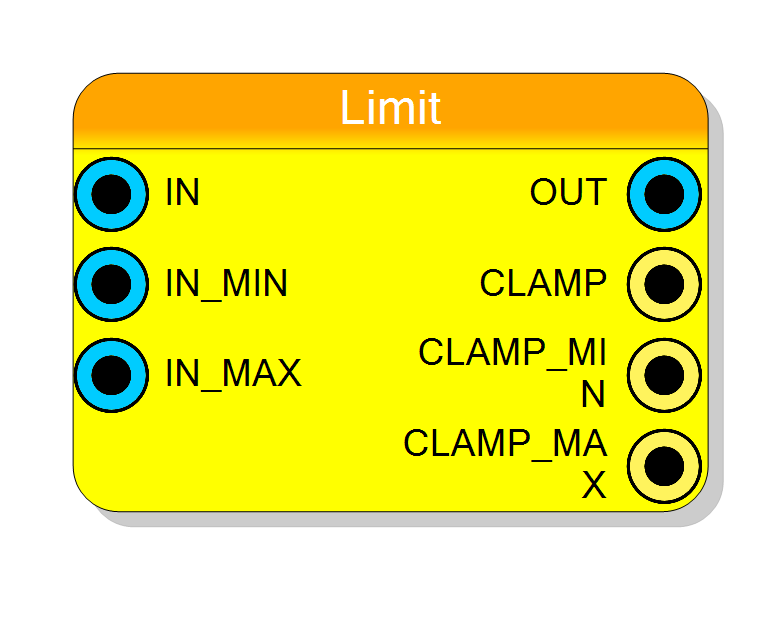
Clamps an input value to a specified range by limiting it between MIN and MAX boundaries. Outputs the clamped value plus three status flags (CLAMP, CLAMP_MIN, CLAMP_MAX) that signal when the input is being actively clamped. Supports signed/unsigned interpretation with optional output register.
Introduction
This block clamps an input value to stay within specified minimum and maximum bounds. Unlike the Between comparator which outputs a boolean, this component outputs the limited value itself, together with three single-bit status flags that indicate whether (and on which side) the input is being clamped:
$$ \mathrm{OUT} = \begin{cases} \mathrm{IN_MIN} & \text{if } \mathrm{IN} < \mathrm{IN_MIN} \ \mathrm{IN} & \text{if } \mathrm{IN_MIN} \leq \mathrm{IN} \leq \mathrm{IN_MAX} \ \mathrm{IN_MAX} & \text{if } \mathrm{IN} > \mathrm{IN_MAX} \end{cases} $$
$$ \mathrm{CLAMP_MIN} = (\mathrm{IN} < \mathrm{IN_MIN}),\quad \mathrm{CLAMP_MAX} = (\mathrm{IN} > \mathrm{IN_MAX}),\quad \mathrm{CLAMP} = \mathrm{CLAMP_MIN} \lor \mathrm{CLAMP_MAX} $$
Pin Description
'1' whenever the input is being clamped on either
side (i.e. CLAMP_MIN OR CLAMP_MAX).
Width: 1 bit.
'1' whenever the input is below IN_MIN and the
output has been forced to IN_MIN.
Width: 1 bit.
'1' whenever the input is above IN_MAX and the
output has been forced to IN_MAX.
Width: 1 bit.
Properties
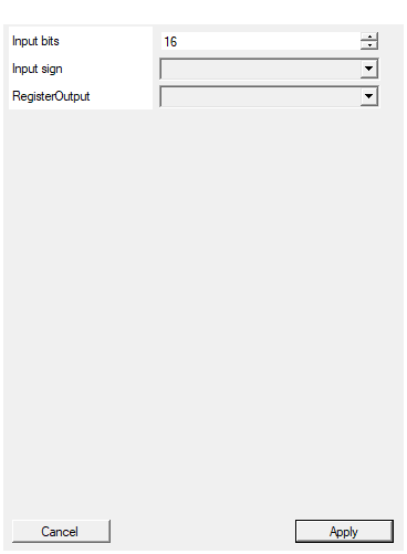
Set the number of bits of the input
Number of bits for all values (IN, IN_MIN, IN_MAX, OUT). Range: 2-2048 bits. All ports must have the same width.Default: 16
Range: 2 – 2048
Select the sign/unsign of the input
Selects input interpretation: UNSIGNED (default) or SIGNED (two’s complement) for all inputs and output.Default: UNSIGNED
Options: UNSIGNED SIGNED
Enable one pipeline stage adding a register
Adds an output register stage. Disable (combinational, zero latency) or Enable (registered, 1 clock cycle latency).Default: Disable
Options: Disable Enable
Functional description
The Limit component performs range limiting (clamping/saturation) on the input value. The output is always within the specified range [IN_MIN, IN_MAX].
Operation Modes
The component compares the input against both boundaries and selects the appropriate output:
- Below range: If IN < IN_MIN, output IN_MIN
- Within range: If IN_MIN ≤ IN ≤ IN_MAX, output IN (pass-through)
- Above range: If IN > IN_MAX, output IN_MAX
Mathematical Expression
$$ \mathrm{OUT} = \max(\mathrm{IN_MIN}, \min(\mathrm{IN}, \mathrm{IN_MAX})) $$
Or equivalently: $$ \mathrm{OUT} = \begin{cases} \mathrm{IN_MIN} & \text{if } \mathrm{IN} < \mathrm{IN_MIN} \ \mathrm{IN} & \text{if } \mathrm{IN_MIN} \leq \mathrm{IN} \leq \mathrm{IN_MAX} \ \mathrm{IN_MAX} & \text{if } \mathrm{IN} > \mathrm{IN_MAX} \end{cases} $$
Status flags
Three single-bit outputs report the clamping state on each cycle:
| Flag | Meaning |
|---|---|
CLAMP_MIN |
'1' while IN < IN_MIN (output forced to IN_MIN). |
CLAMP_MAX |
'1' while IN > IN_MAX (output forced to IN_MAX). |
CLAMP |
CLAMP_MIN OR CLAMP_MAX – any active clamping. |
When RegisterOutput = Enable, the flags are registered with the same
one-cycle latency as OUT, so they remain aligned with the clamped value.
Example (8-bit unsigned)
With IN_MIN = 10 and IN_MAX = 200:
| IN | OUT | CLAMP | CLAMP_MIN | CLAMP_MAX |
|---|---|---|---|---|
| 5 | 10 | 1 | 1 | 0 |
| 50 | 50 | 0 | 0 | 0 |
| 250 | 200 | 1 | 0 | 1 |
Simulation waveform
The trace below shows a sine wave A0[15:0] driven into the Limit block.
PClamp[15:0] is the clamped output (top and bottom of the sine are cut
flat). BClampMax is high while the sine exceeds IN_MAX, BClampMin
is high while it falls below IN_MIN, and BClamp is the OR of the two.
Use in Signal Processing
This component is commonly used for:
- Saturation arithmetic: Preventing overflow in fixed-point calculations
- Dynamic range limiting: Constraining signal amplitudes
- Protection circuits: Ensuring values stay within safe operating ranges
Latency and Timing
| RegisterOutput | Latency (clock cycles) |
|---|---|
| Disable | 0 |
| Enable | 1 |
Typical use cases
- Saturation arithmetic in DSP applications
- Preventing overflow in accumulator chains
- Audio/video signal limiting
- Constraining control signals to valid ranges
- Input protection and validation