
RF FM Modulator
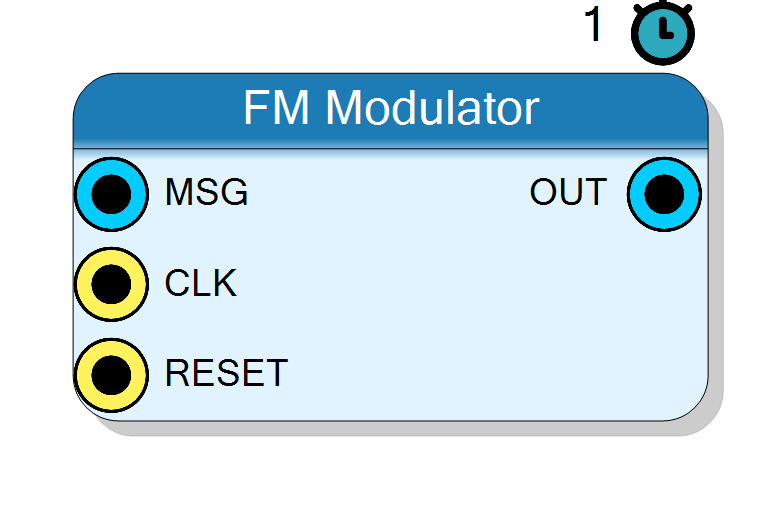
Frequency modulator. Internal carrier: an NCO whose instantaneous frequency is Fc + Deviation*msg, emitting a real cosine. External carrier: a quadrature carrier pair (CARRIER_I/CARRIER_Q) rotated by the integrated FM phase, emitting a real output at the carrier frequency. Real message in, real modulated signal out.
Introduction
The FM Modulator shifts the carrier’s instantaneous frequency in proportion to the message. The Carrier Source property selects the implementation:
-
Internal - an NCO whose frequency is the centre frequency plus a message-proportional deviation, read out as a real cosine:
f_inst[n] = Fc + Deviation * msg_norm[n] phase[n] = phase[n-1] + PHASE_INCR + dinc[n] y[n] = cos(phase[n])where
PHASE_INCR = round(Fc / Fs * 2^32)is the centre-frequency phase step anddinc[n] = (DEV_INCR * msg) >> (InputSize-1)is the deviation step, withDEV_INCR = round(Deviation / Fs * 2^32)the phase increment at full-scale message. -
External - the carrier is supplied as a quadrature pair and rotated by the integrated FM phase
psi(you cannot FM a single real waveform, hence an I/Q carrier):psi[n] = psi[n-1] + dinc[n] y[n] = CARRIER_I * cos(psi) - CARRIER_Q * sin(psi)(
sin(x) = cos(x - pi/2)read from the same cosine LUT). The result is a real output at the external carrier’s frequency, frequency-modulated by the message.
This block uses the standard property grid (no custom designer).
Pin Description
InputSize bits, normalised to full scale;
full-scale message gives the peak Deviation frequency shift.
InputSize + 1 bits.
InputSize bits.
InputSize bits.
Properties
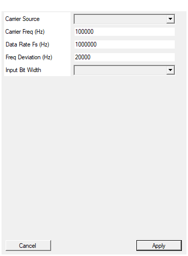
Internal: NCO at Carrier Freq. External: quadrature CARRIER_I/CARRIER_Q pins.
Internal: NCO at Carrier Freq, real cosine out. External: quadrature CARRIER_I/CARRIER_Q pins rotated by the FM phase. Default Internal. Changing it redesigns the core (pin set changes).Default: Internal
Options: Internal External
Internal NCO centre frequency.
Internal NCO centre frequency in Hz (Internal mode). The centre phase wordround(Fc / Fs * 2^32) is baked at compile time. Default
100000.
Default: 100000
Sample rate.
Sample rate in Hz. Used to convert Carrier Freq and Deviation to phase words. Default 1000000.Default: 1000000
Peak frequency deviation at full-scale message.
Peak frequency deviation in Hz at full-scale message. Baked asround(Deviation / Fs * 2^32). Default 20000.
Default: 20000
Message / carrier bit width.
Message / carrier bit width. Range 4 to 30, default 16.Default: 16
Options: 4 5 6 7 8 9 10 11 12 13 14 15 16 17 18 19 20 21 22 23 24 25 26 27 28 29 30
Usage
Frequency-to-phase mapping
The phase accumulator is 32-bit; a phase increment w corresponds to a
frequency f = w / 2^32 * Fs. Both the centre-frequency word and the
full-scale-deviation word are computed by the plugin from the Hz properties:
PHASE_INCR = round(Fc / Fs * 2^32) (baked constant)
DEV_INCR = round(Deviation / Fs * 2^32) (baked constant)
dinc[n] = (DEV_INCR * msg[n]) >> (InputSize - 1) (per-sample, signed)
Fc, Fs and Deviation are static properties resolved at compile time (no frequency pins).
Cosine LUT
The internal cosine table has LUT_BITS = 12 (4096 entries), amplitude
InputSize-bit (fm_mod_cos.inc). Internal mode reads cos(phase) from it;
External mode reads both cos(psi) and sin(psi) from it to rotate the I/Q
carrier.
Bit widths
MSG,CARRIER_I,CARRIER_Q: signedInputSizebits.OUT: signedInputSize + 1bits (1 bit of output growth).- External-mode product is
2*InputSize + 1bits, right-shifted byInputSize - 1before the output.
Latency and throughput
#pragma HLS PIPELINE II=1: one output sample per clock.- All ports use the
ap_noneinterface (no ready/valid handshake).
Reset
RESET is the HLS synchronous reset (ap_rst). It clears the phase
accumulator (Internal phase / External psi).
Typical applications
- NBFM / WBFM signal generation from a baseband message (Internal).
- Re-modulating an existing quadrature carrier with a new message without regenerating the carrier tone (External).
Resources & Timing
-
Latency: 1 clock cycle (II=1)
-
Throughput: 1 sample per clock (II=1)
Implemented with Vitis HLS. A 4096-entry (LUT_BITS=12) cosine ROM and a 32-bit phase accumulator. Internal mode: one multiply (DEV_INCRmsg) plus a LUT read. External mode: adds the two-multiply I/Q rotation (CARRIER_Icos
- CARRIER_Q*sin). Static params (external flag, PHASE_INCR, DEV_INCR, InputSize) drive the HLS unique name.