
Serial Bus - UART
Universal Asynchronous Receiver/Transmitter (UART) for serial communication. Full-duplex operation with configurable baud rate, data width, and parity. Supports standard RS-232 compatible serial protocols.
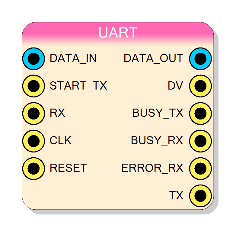
Introduction
The UART block implements a Universal Asynchronous Receiver/Transmitter for serial communication without a shared clock signal.
UART uses only two wires for bidirectional communication:
- TX - Transmit data output (master to slave)
- RX - Receive data input (slave to master)
Key features:
- Configurable baud rate (300 to 3,000,000 bps)
- Configurable data width (5-9 bits)
- Optional parity (None, Even, Odd)
- Independent TX and RX channels
- Error detection for framing and parity errors
Pin Description
Transmit busy status.
- LOW: Ready to accept new data
- HIGH: Transmission in progress
Receive busy status.
- LOW: Idle, waiting for start bit
- HIGH: Reception in progress
Receive error flag. Goes HIGH if any error detected:
- Start bit error (not LOW)
- Parity mismatch
- Stop bit error (not HIGH) Valid when DV pulses.
Properties
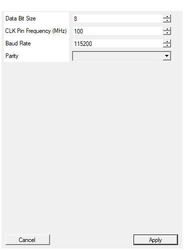
Set the number of data bits per word (5-9)
Default: 8
Range: 5 – 9
Set the input clock frequency in MHz
Default: 100
Range: 1 – 500
Set the communication baud rate in bits per second
Communication speed in bits per second. Both transmitter and receiver must use the same rate.
Standard baud rates:
- 9600: Common for slow devices
- 19200: Legacy standard
- 38400: Moderate speed
- 57600: Faster legacy
- 115200: Most common modern default
- 230400: High speed
- 460800: Very high speed
- 921600: Maximum standard rate
- 1000000+: Non-standard high speeds
Actual rate may differ slightly due to integer clock division.
Default: 115200
Range: 300 – 3000000
Select parity mode for error detection
Error detection mode.
- None: No parity bit, 1 stop bit
- Even: Parity bit makes total 1s even
- Odd: Parity bit makes total 1s odd
Parity adds one bit to each frame and provides basic error detection. For critical applications, consider higher-level protocols with CRC.
Default: None
Options: None Even Odd
Number of data bits per word (5-9). Most common setting is 8 bits.
Standard configurations:
- 7 bits: ASCII text (legacy)
- 8 bits: Most common, binary data
- 9 bits: With address/data flag (Multidrop)
Frequency of the CLK input in MHz. Used to calculate baud rate timing.
Must be at least 16 times the baud rate for proper operation. For 115200 baud, minimum CLK is ~1.85 MHz.
Typical values:
- 50 MHz: V2495 default
- 80 MHz: DT5550 default
- 100-200 MHz: High-speed designs
Functional description
UART transmits data asynchronously without a clock signal. Both transmitter and receiver must be configured for the same baud rate and data format.
Data Frame Structure
Each data frame consists of:
- Start bit: Line goes LOW to signal start of transmission
- Data bits: 5-9 bits, LSB first
- Parity bit (optional): Even or odd parity for error detection
- Stop bit: Line returns HIGH for at least one bit period
Baud Rate
The baud rate determines how many bits are transmitted per second. Common standard rates include:
| Baud Rate | Bit Period |
|---|---|
| 9600 | 104.2 us |
| 19200 | 52.1 us |
| 38400 | 26.0 us |
| 57600 | 17.4 us |
| 115200 | 8.7 us |
| 230400 | 4.3 us |
| 460800 | 2.2 us |
| 921600 | 1.1 us |
The UART generates internal timing from the CLK input using:
$$ T_{bit} = \frac{f_{CLK}}{BaudRate} $$
Oversampling
The receiver uses 16x oversampling to accurately detect the center of each bit, providing tolerance for baud rate mismatch between devices (typically up to 3% difference is acceptable).
Parity
Parity provides simple error detection:
- None: No parity bit transmitted
- Even: Parity bit makes total number of 1s even
- Odd: Parity bit makes total number of 1s odd
If received parity doesn’t match calculated parity, Error RX goes high.
Transmission Flow
- Load data on Data In
- Pulse Start TX high
- Busy TX goes high during transmission
- TX outputs start bit, data bits, parity (if enabled), stop bit
- Busy TX goes low when complete
Reception Flow
- RX line monitored for start bit (HIGH to LOW transition)
- Busy RX goes high during reception
- Data bits sampled at center of each bit period
- Parity checked (if enabled)
- Stop bit verified
- DV pulses high when data is ready
- Read received data from Data Out
- Check Error RX for framing or parity errors
Reset Behavior
The Reset input is active high:
- TX line held HIGH (idle)
- Busy TX held HIGH (not ready)
- Busy RX held LOW
- After reset release, Busy TX goes LOW on next CLK