
Custom Packet DMA
User-defined packet readout block with DMA transfer support. High-speed FIFO-based list mode transfer with customizable data format for DT/R5560 family.
Introduction
The Custom Packet DMA block is a variant of the Custom Packet block with DMA (Direct Memory Access) transfer support. It provides significantly higher data throughput by using dedicated DMA channels available on the DT5560 and R5560 family boards.
Using the graphical Packet Creator tool, you define the exact structure of data packets that are pushed into an output FIFO and transferred to the host PC via DMA.
The packet data can be read via Resource Explorer (with file dump capability) or programmatically using the SciSDK library.
SciSDK Documentation: https://nuclearinstruments.github.io/SCISDK/
Pin Description
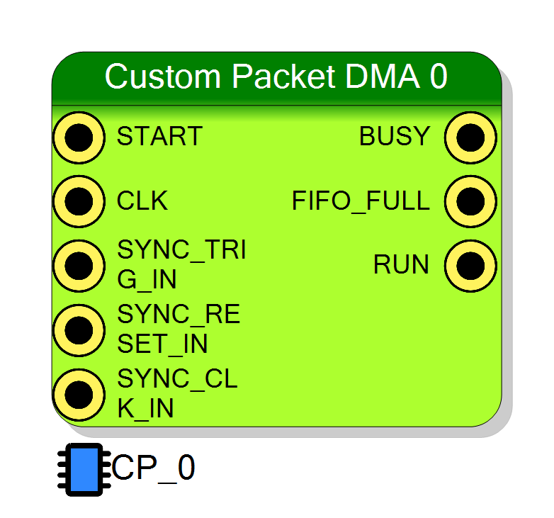
Packet trigger input. A rising edge latches all INx values and initiates packet transfer to the FIFO.
Ignored while BUSY is HIGH.
User-defined input signals. The number and size of inputs is determined by the Packet Layout configuration.
All inputs are latched simultaneously on the rising edge of START. Data must be valid one clock cycle after START.
Properties
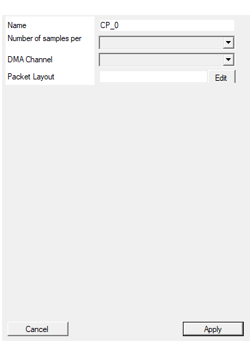
Set the name of the endpoint
Default: CP_0
Set the number of samples stored for each acquisition
Default: 1024
Options: 128 256 512 1024 2048 4096 8192 16384 32768 65536 131072 262144 524288
Select DMA Channel. DMA channels must me used by only one endpoint in the entire design
Default: 0
Options: 0
Packet Layout
Output FIFO size in 32-bit words. Available values: 128, 256, 512, 1024, 2048, 4096, 8192, 16384, 32768, 65536, 131072, 262144, 524288.
Larger buffers reduce the risk of overflow but use more FPGA resources. Default: 1024
Selects the DMA channel for high-speed data transfer.
Important: Each DMA channel can only be used by ONE endpoint in the entire design. If you have multiple Custom Packet DMA blocks, each must use a different channel.
Available channels depend on the board model.
Opens the Packet Creator graphical editor. Define the packet structure by adding rows and elements.
Each row is 32 bits. Elements can be:
- Constant: Fixed header/sync value
- Timecode: Internal timestamp
- Packet Counter: Sequential number
- Input: Data from input pins
- Packet Size: Total packet length
Multiple elements can share a row if their combined size ≤ 32 bits. Use slicing for inputs larger than 32 bits.
Usage
DMA Advantage
The DMA transfer mode provides higher data throughput compared to the standard Custom Packet block:
┌──────────────────────────────────────────────────────────────────┐
│ Custom Packet DMA Data Flow │
│ │
│ IN0 ────────►┌──────────────┐ ┌─────────────┐ │
│ IN1 ────────►│ │ │ FIFO │ │
│ IN2 ────────►│ Packet │────►│ Buffer │ │
│ ... │ Builder │ │ │ │
│ START ─────►│ │ └──────┬──────┘ │
│ └──────────────┘ │ │
│ ▼ │
│ ┌─────────────┐ │
│ │ DMA │────► PC │
│ │ Engine │ (High Speed) │
│ └─────────────┘ │
└──────────────────────────────────────────────────────────────────┘
The DMA engine handles data transfer in the background, reducing CPU overhead and enabling sustained high-rate data acquisition.
How It Works
The Custom Packet DMA operates identically to the standard Custom Packet:
- When START goes HIGH, all input signals are latched simultaneously
- The latched data is packaged according to your defined format
- The packet is pushed into the output FIFO
- The DMA engine transfers packets to the PC at high speed
Important: The module latches inputs on the START rising edge. Data must be valid one clock cycle after START is issued.
DMA Channel Selection
The DT5560/R5560 boards provide multiple DMA channels. Each Custom Packet DMA instance must use a unique DMA channel - no two endpoints can share the same channel.
Select the DMA channel in the block properties. Available channels depend on the specific board model.
Packet Creator Tool
The Packet Creator is identical to the standard Custom Packet. Access it by clicking the Edit button next to the “Packet Layout” property.
For complete documentation on using the Packet Creator, see the Custom Packet documentation.
Each packet consists of one or more 32-bit rows. Each row can contain:
| Element Type | Description |
|---|---|
| Constant | Fixed 32-bit value (useful as header/sync word) |
| Timecode | Internal timestamp counter |
| Packet Counter | Sequential packet number |
| Packet Size | Total packet size in words |
| Input | Data from input pins |
Multi-Board Synchronization
The Custom Packet DMA includes synchronization inputs for multi-board setups:
| Input | Function |
|---|---|
| SYNC_TRIG_IN | External trigger that increments the trigger counter |
| SYNC_RESET_IN | Resets trigger counter and external timestamp |
| SYNC_CLK_IN | External timestamp clock |
These allow multiple boards to share a common timebase and trigger numbering.
Status Outputs
| Output | Description |
|---|---|
| BUSY | HIGH while packet transfer is in progress. Inputs and START are ignored. |
| FIFO_FULL | HIGH if buffer overrun occurred (data loss). |
| RUN | HIGH when acquisition is enabled by software. |
Software Integration with SciSDK
The Custom Packet DMA is fully supported by SciSDK. For complete documentation see: SciSDK Custom Packet Guide
Resource Explorer can also read and dump Custom Packet DMA data to file.
Available Parameters
| Parameter | Access | Description |
|---|---|---|
acq_len |
R/W | Maximum samples per FIFO read (default: 1024) |
acq_mode |
R/W | blocking or non-blocking |
timeout |
R/W | Timeout in milliseconds (blocking mode) |
data_processing |
R/W | raw or decode mode |
Available Commands
| Command | Description |
|---|---|
start |
Begin acquisition |
stop |
Stop acquisition |
reset |
Reset counters and FIFO |
flush |
Clear FIFO content |
C/C++ Example
c
#include "SciSDK_DLL.h"
// Allocate decoded buffer (1024 packets)
SCISDK_CP_DECODED_BUFFER *buffer;
SCISDK_AllocateBufferSize("board0:/MMCComponents/CP_0",
T_BUFFER_TYPE_DECODED,
(void**)&buffer, _sdk, 1024);
// Configure decode mode
SCISDK_SetParameterString("board0:/MMCComponents/CP_0.data_processing",
"decode", _sdk);
// Start acquisition
SCISDK_ExecuteCommand("board0:/MMCComponents/CP_0.start", "", _sdk);
// Read data (DMA provides higher throughput)
while (running) {
int ret = SCISDK_ReadData("board0:/MMCComponents/CP_0",
(void*)buffer, _sdk);
if (ret == NI_OK) {
for (int i = 0; i < buffer->info.valid_data; i++) {
// Process packet...
}
}
}
// Stop and free
SCISDK_ExecuteCommand("board0:/MMCComponents/CP_0.stop", "", _sdk);
SCISDK_FreeBuffer("board0:/MMCComponents/CP_0",
T_BUFFER_TYPE_DECODED, (void**)&buffer, _sdk);
Python Example
python
from scisdk.scisdk import SciSDK
sdk = SciSDK()
sdk.AddNewDevice("usb:10500", "dt5560", "board0", "RegisterFile.json")
# Allocate buffer
res, buf = sdk.AllocateBufferSize("board0:/MMCComponents/CP_0",
sdk.T_BUFFER_TYPE_DECODED, 1024)
# Configure
sdk.SetParameter("board0:/MMCComponents/CP_0.data_processing", "decode")
# Start and read
sdk.ExecuteCommand("board0:/MMCComponents/CP_0.start", "")
while True:
res, buf = sdk.ReadData("board0:/MMCComponents/CP_0", buf)
if res == 0:
for packet in buf.data:
# Process packet...
print(packet)
When to Use DMA vs Standard Custom Packet
| Use Case | Recommended Block |
|---|---|
| High event rates (>100 kHz) | Custom Packet DMA |
| Maximum throughput required | Custom Packet DMA |
| DT5560/R5560 boards | Custom Packet DMA |
| V2495 or other boards | Custom Packet (standard) |
| Limited DMA channels available | Custom Packet (standard) |
Resources & Timing
-
Latency: 1 clock cycle from START to data latch
-
Throughput: High-speed DMA transfer to PC
- Uses BRAM for FIFO storage plus DMA engine
- DMA provides significantly higher throughput than standard Custom Packet
- Available only on DT5560/R5560 family boards
- Data readable via Resource Explorer or SciSDK
- Resource Explorer can dump packets to file
Supported Boards
- DT5560
- DT5560SE
- R5560
- R5560SE