
RF Halfband Interpolator (fixed)
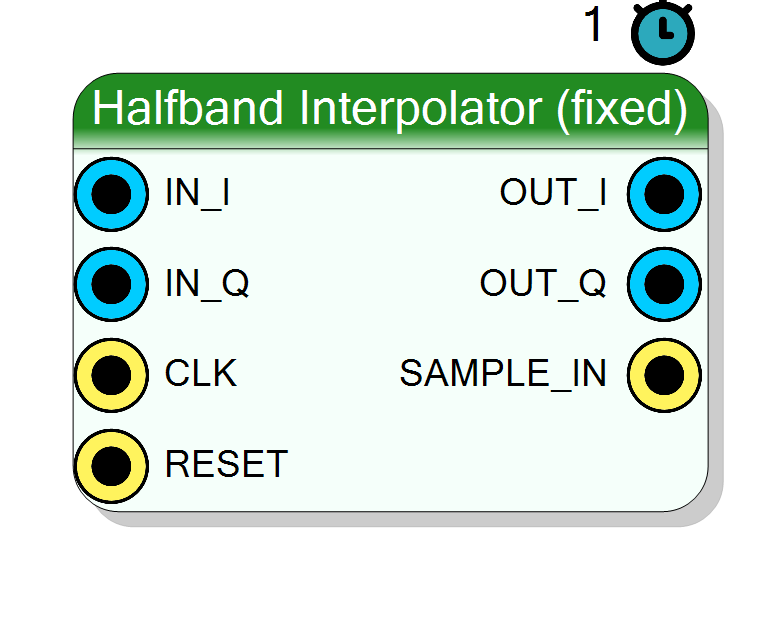
Complex I/Q halfband FIR filter that interpolates by exactly 2 with coefficients computed by the plugin and baked into the netlist. It zero-stuffs one sample per input and suppresses the image with an Fs/4 halfband, the efficient rate-doubling stage of a multistage DUC.
Introduction
The Halfband Interpolator (fixed) block doubles the sample rate of a complex baseband stream. It is the workhorse rate-increase stage of a multistage Digital Up-Converter (DUC).
Interpolation-by-2 is done in the classic two-step way: zero-stuff (insert one zero sample between every pair of input samples), then low-pass filter to remove the spectral image the zero-stuffing creates. The image sits above Fs/4 of the fast-rate spectrum, so the natural anti-image filter is again a halfband — cutoff at Fs/4, every second coefficient zero (except the centre), symmetric taps. That makes the halfband the cheapest FIR for a 2:1 interpolation just as it is for decimation.
slow rate fast (output) rate
IN_I ─┐ up 2 ┌── OUT_I
│ [ 0-stuff│
IN_Q ─┘ + HB ] └── OUT_Q
└── SAMPLE_IN (asserted when a new input is taken)
The block runs at the fast (output) clock. On alternate clocks it
consumes a real input sample; in between it injects a zero. The coefficients
are computed by the plugin at design time (windowed-sinc at fc = 0.25*Fs,
Hamming window, unity DC gain), quantised to CoefSize signed bits and
stored as a NumTaps * CoefSize bit constant in the VHDL.
For a run-time programmable version see
Component_HalfbandInterpolatorProgrammable (halfband_interp_prog).
Pin Description
Properties
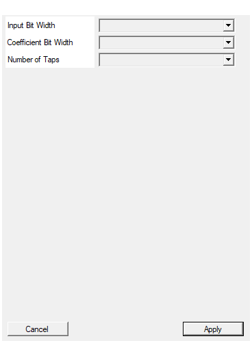
Bit width of each I/Q input sample (signed).
Bit width of each signed I / Q input sample. Range 4 to 32, default 16. Changing it triggers a redesign.Default: 16
Options: 4 5 6 7 8 9 10 11 12 13 14 15 16 17 18 19 20 21 22 23 24 25 26 27 28 29 30 31 32
Bit width of each coefficient (signed).
Bit width of each signed coefficient. Choices 10, 12, 14, 16, 18, 20, 24; default 16. A larger value lowers the image / stop-band floor at the cost of DSP width.Default: 16
Options: 10 12 14 16 18 20 24
Number of taps (canonical halfband: 4k+3 = 7, 11, 15, 19, 23, 27, 31, …).
Number of filter taps (filter order =NumTaps - 1). Choices
7, 11, 15, 19, 23, 27, 31, 39, 47, 63; default 15. Use a
canonical halfband length 4k+3 so the even taps fall on the sinc
zeros. More taps deepen image rejection at the cost of DSPs.
Default: 15
Options: 7 11 15 19 23 27 31 39 47 63
Usage
Why halfbands are the efficient DUC stages
A transmitter builds up to the DAC rate through a cascade of cheap 2:1 interpolators (often finishing into a CIC). Each halfband stage only has to suppress the single image introduced by its own x2 upsampling, and the Fs/4 cutoff zeroes half the taps, so the DSP cost per stage is minimal. Chain several instances for x4, x8, x16 … interpolation.
Zero-stuff-and-filter model
Let x_c be the slow-rate input for channel c in {I, Q}. The block
forms a fast-rate stream u_c by inserting zeros,
u_c[2m] = x_c[m]
u_c[2m+1] = 0
then filters it with the halfband:
y_c[n] = sum_{k=0..NumTaps-1} h[k] * u_c[n-k]
Every output clock produces a valid OUT_I/OUT_Q at the fast rate.
Coefficient generation (fixed variant)
h_ideal[n] = 2*fc * sinc(2*fc*(n - (N-1)/2)), fc = 0.25
w[n] = 0.54 - 0.46 * cos(2*pi*n / (N-1)) (Hamming)
h[n] = h_ideal[n] * w[n]
normalised so sum h[n] = 1 and quantised to signed CoefSize-bit
integers. The even-offset taps land on the sinc zeros automatically. Use
a canonical halfband length 4k+3 (7, 11, 15, 19, 23, 27, 31, …).
Passband gain note
The coefficients are normalised to unity DC gain, but half of the
fast-rate samples entering the filter are the inserted zeros. The
interpolated envelope therefore comes out at roughly half amplitude.
If you need to preserve level through the interpolation, apply a gain of
2 downstream (or scale the coefficients), the usual convention being
a factor-of-L gain in an interpolate-by-L filter.
Bit widths
Data is treated as signed two’s complement.
IN_I,IN_Q: signedInputSizebits (slow-rate samples).- internal product :
InputSize + CoefSizebits. OUT_I,OUT_Q: signedInputSize + CoefSize + 8bits (fast rate).
The extra 8 accumulator bits (ACC_GROWTH = 8) prevent overflow.
SAMPLE_IN / strobe behaviour
Unlike the decimator, the interpolator’s rate strobe is about the
input side. SAMPLE_IN is an output that is asserted on the
fast-rate clocks where a new IN_I/IN_Q sample is actually consumed (the
other clocks insert a zero). The producer of the slow-rate data uses it as
an “advance now” enable: present the next input word and pulse your slow
producer only on the clocks where SAMPLE_IN is high. The internal
consume phase starts true after reset, so the first post-reset clock
takes an input sample. OUT_I/OUT_Q are valid on every clock at the
fast rate.
Latency and reset
#pragma HLS PIPELINE II=1: one output pair per clock (fast rate).- 1-clock reported latency (delay-line update + MAC tree).
- Data ports use
ap_none; the coefficient bus usesap_stable. RESET(ap_rst) clears the delay lines and re-arms theconsumephase.
Typical applications
- 2:1 up-sampling stages of a multistage DUC ahead of the mixer / CIC.
- Bringing a baseband waveform generator up toward the DAC sample rate.
- Cascade instances for x4, x8, x16 interpolation.
Resources & Timing
-
Latency: 1 clock cycle (reported)
-
Throughput: Runs at the fast (output) rate: 1 output pair per clock (II=1). A new input sample is consumed on every second clock (input rate = output rate / 2), flagged by SAMPLE_IN.
Implemented with Vitis HLS. Delay lines and coefficient array are fully partitioned and the MACC loop unrolled, so up to NumTaps DSP48 slices per channel are inferred. Because the coefficients are compile-time constants, Vivado prunes the ~half of taps that are zero, giving the halfband DSP saving. Output is ~half amplitude (unity-DC-gain filter on zero-stuffed data) — apply a gain of 2 downstream to preserve level. Fixed 2:1 rate change is built into the block.