
Gated Integrator (TM)
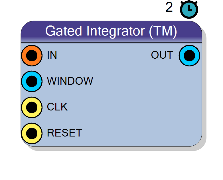
Time-multiplexed gated integrator with programmable integration window. Sums a configurable number of consecutive samples from TM data streams, producing a single integrated output value. Uses BRAM-based delay line to store recent samples. Pipeline latency: 2 cycles.
Introduction
This block performs gated (windowed) integration of time-multiplexed (TM) input streams, summing a programmable number of consecutive samples to produce a single accumulated output value.
On every rising edge of CLK, the component computes:
$$ \mathrm{OUT} = \sum_{k=0}^{W-1} \mathrm{IN}(n-k), $$
where $W$ is the integration window (number of sample phases) set by the
WINDOW input. Unlike a moving average, the output is a single scalar value
(not time-multiplexed), representing the integrated energy over the window.
Pin Description
Input bits × TM Factor
All TM phases are buffered and available for integration.
Integration window size, scalar (not TM). Width: Calculated as ceil(log2(Window Max + 1)) bits. Valid range: 1 to Window Max.
Specifies the number of sample phases to integrate (NOT clock cycles). For TM Factor = N, Window = W integrates W/N clock cycles of data.
Properties
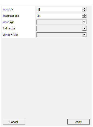
Set the number of bits of the input per sample
Number of bits per input sample ($N_\text{in}$). Range: 4 – 32. Each TM sample is stored in the circular buffer with this width.Default: 16
Range: 4 – 32
Set the number of bits of the integrator output
Number of bits of the integrator accumulator and output ($N_\text{integ}$). Range: 16 – 64.
Must be large enough to prevent overflow:
$$ N_\text{integ} \geq N_\text{in} + \log_2(W_\text{max}) $$
Example: 16-bit input, Window Max = 1024 → need ≥ 16 + 10 = 26 bits.
Default: 48 bits (suitable for most applications).
Default: 48
Range: 16 – 64
Select the sign/unsign of the input
Arithmetic type of the input signal:
UNSIGNED→ Non-negative samplesSIGNED→ Two’s complement samples
The integrator accumulator is always SIGNED to handle sum growth correctly.
Default: UNSIGNED
Options: UNSIGNED SIGNED
Select the Time Multiplexing factor (samples per word)
Number of time-multiplexed phases (samples per clock). Allowed values: 2, 4, 8, 16, 32.
All TM phases share the same circular buffer and contribute to the integration window. Window is specified in sample phases, not clock cycles.
Default: 4
Options: 2 4 8 16 32
Maximum window size for programmable gated integration (in sample phases). Stored in BRAM.
Maximum integration window size (buffer depth), stored in BRAM. Allowed values: 64, 128, 256, 512, 1024.
BRAM usage ≈ (Input bits) × (Window Max) / 18k bits per TM lane.
The WINDOW input can dynamically select any window size from
1 to Window Max without reconfiguration.
Default: 64
Options: 64 128 256 512 1024
Functional description
The component is implemented using Xilinx HLS (High-Level Synthesis) and uses a BRAM-based circular buffer to store recent samples across all TM phases.
Window configuration
- WINDOW: Input specifying integration window in sample phases (not clock cycles!)
- Window Max: Maximum window size (design-time BRAM allocation)
- Valid window range: 1 to Window Max
For a TM Factor of N:
- Window of W phases = W/N clock cycles of data
- Example: TM Factor = 4, Window = 64 → integrates 16 clock cycles of data
Integration operation
The integrator maintains:
- Circular buffer of recent samples (depth = Window Max)
- Running sum accumulator (width = Integrator bits)
- Sliding window logic to add new samples and subtract old ones
The output represents:
$$ \text{OUT}[n] = \sum_{i=0}^{W-1} \text{IN}[n \cdot N + i] $$
where $N$ = TM Factor, and the sum spans $W$ consecutive TM sample phases.
Fixed-point precision
- Input bits: 4-32 bits (configurable sign)
- Integrator bits: 16-64 bits (always SIGNED to accommodate growth)
- Output: Single scalar value (NOT time-multiplexed)
Size the integrator bit width to prevent overflow:
$$ N_\text{integ} \geq N_\text{in} + \log_2(W_\text{max}) $$
Mathematical background
The gated integrator is equivalent to a finite impulse response (FIR) filter with all coefficients = 1:
$$ y[n] = \sum_{k=0}^{W-1} x[n-k] $$
In the frequency domain:
$$ H(z) = \sum_{k=0}^{W-1} z^{-k} = \frac{1 - z^{-W}}{1 - z^{-1}} $$
This provides:
- Lowpass filtering with nulls at $f_k = k \cdot f_s / W$
- Linear phase response (symmetric window)
- Gain = W at DC
Timing
The HLS-generated IP has a fixed pipeline latency of 2 clock cycles:
| Property | Latency (clock cycles) |
|---|---|
| Gated Integrator (TM) | 2 |
Total system delay: T_delay = 2 × T_CLK.
Note: The integration itself spans $W$ sample phases, but the computation completes 2 clock cycles after the last sample enters the window.
Typical use cases
- Pulse-height analysis: Integrating detector pulses to measure energy
- Charge integration: Summing ADC samples over a fixed gate window
- Peak detection: Accumulating signal around threshold crossings
- Nuclear/particle physics: Gated integration for energy spectroscopy
Waveform example
Example with TM Factor = 4, Window = 8 phases (2 clock cycles), Input = [10, 10, 10, 10, …].
Note: OUT = sum of 8 samples = 10 × 8 = 80, available 2 cycles after last sample.