
Dual Averaged Oscilloscope
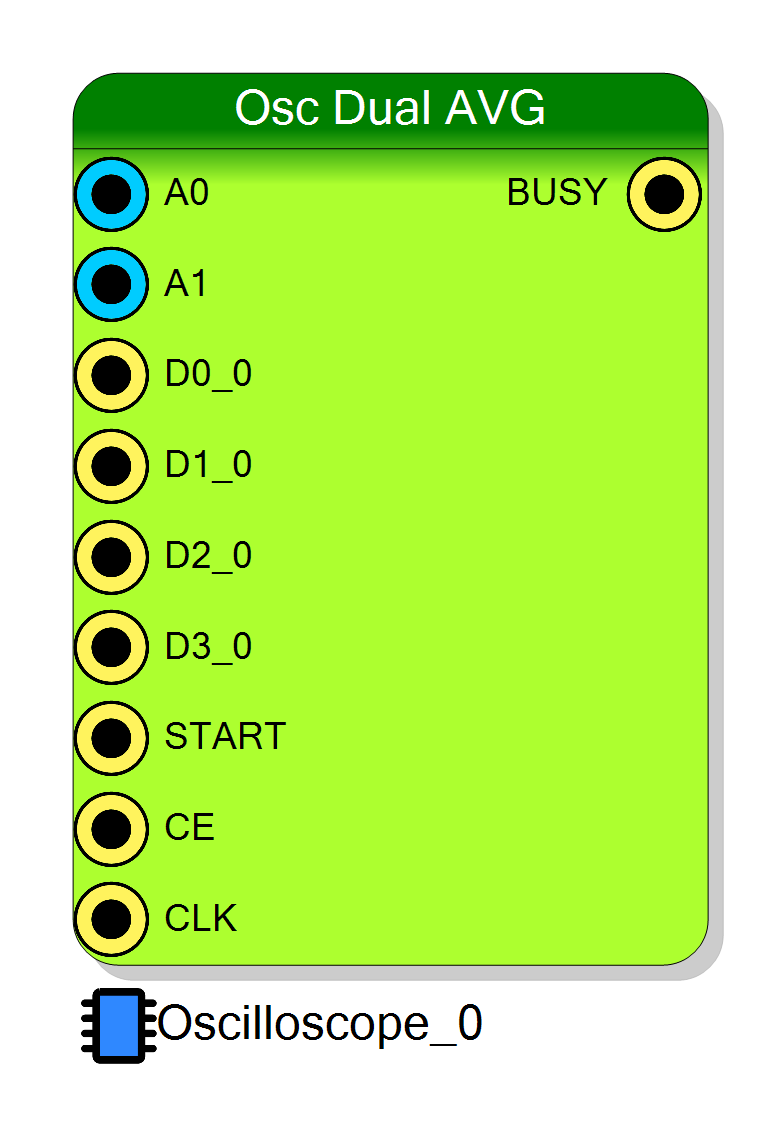
Dual Averaged Oscilloscope is a multi-channel oscilloscope IP core for Xilinx-7 devices that acquires up to 32 simultaneous analog channels plus up to 4 groups of digital lines (optional). The Dual architecture packs two analog samples per 32-bit RAM word (pairing channels 0–1, 2–3, …). If digital inputs are enabled each analog width is reduced to 14 bits so a word holds 14-bit A, 14-bit B and 4 digital bits (D0…D3). Otherwise each word carries two full 16-bit samples. When a decimation factor CONFIG_DECIMATOR = D > 0 is programmed the core performs an on-the-fly box-car average over $N = 2^{D}$ consecutive raw samples (per channel and per digital line using a peak holder for digital). Fast digital transitions inside the averaging window are preserved via a bitwise-OR peak holder ensuring glitch-free mixed-signal captures. The design is not time multiplexed; channel pairs are sampled concurrently and packed combinationally.
Introduction
Principle of Operation
Let
- $f_s$ = raw input sampling frequency (write clock)
- $D = \text{CONFIG_DECIMATOR} \in [0, 20]$
- $N = 2^{D}$ = averaging/decimation window length
- $x_k(i)$ = raw sample $k$ of analog channel $i$
- $y_m(i)$ = averaged/decimated output sample $m$ of channel $i$
When $D = 0$: $y_m(i) = x_m(i)$ (no averaging).
When $D > 0$: the arithmetic mean of $N$ consecutive raw samples is stored:
$$ y_m(i) = \frac{1}{N}\sum_{k=0}^{N-1} x_{mN + k}(i) $$
An accumulator with width $\text{Wordsize} + D$ per channel collects the
partial sum. When the free-running decimation counter returns to zero
(counterDecimator = 0) the accumulator is right-shifted by $D$ (division
by $N$) and cleared.
Dual Packing (32-bit Word Optimization)
Each memory word represents a channel pair: Pair index $p = \lfloor i/2 \rfloor$ packs channel $2p$ and channel $2p+1$.
-
Digital Disabled (two full 16-bit averaged samples):
[31:16] = Channel (2p+1) averaged sample [15:0 ] = Channel (2p) averaged sample -
Digital Enabled (two 14-bit averaged samples + 4 peak-held bits):
[31] = D3_p [30] = D2_p [29] = D1_p [28] = D0_p [27:14] = Channel (2p+1) averaged sample (14 bits) [13:0 ] = Channel (2p) averaged sample (14 bits)
When digital is enabled each analog result is truncated (or rounded, per implementation option) to 14 bits before packing.
Digital Peak Holder (Within Averaging Window)
For each digital line inside the window of length $N$:
$$ d^{\text{PH}} = \bigvee_{k=0}^{N-1} d_k $$
Even a single-cycle pulse is preserved. With frequent toggling a digital bit may remain high in the averaged record.
Pin Description
000).
CLK_WRITE).
Properties
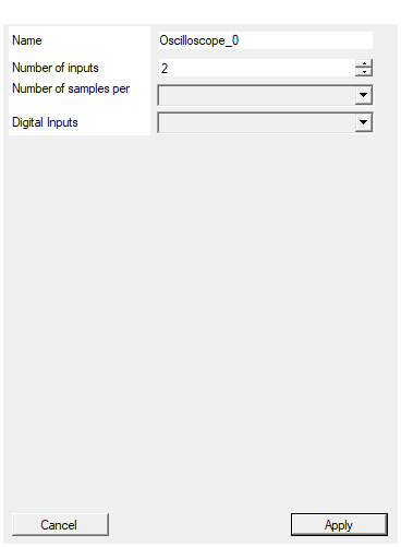
Set the name of the endpoint
Logical endpoint name used in register map; change if multiple oscilloscopes instantiated.Default: Oscilloscope_0
Set the number of input to the virtual block
Number of analog input channels (1 – 32). Must be even (channels handled in pairs).Default: 2
Range: 1 – 32
Set the number of samples stored for each acquisition
Circular buffer length per channel (power of two between 128 and 16384).Default: 1024
Options: 128 256 512 1024 2048 4096 8192 16384
Enable/Disable Digital Inputs
Enable/Disable 4 digital lines. When enabled, analog width shrinks to 14 bits to fit (14+14+4) packing.Default: Enabled
Options: Enabled Disabled
⚙️ Detailed Timing
Event Sequence
- ARM (
CONFIG_ARM0→1) clears decimation counter, accumulators, write pointers and arms the engine. - Raw Sampling: every clock period $T_{\text{CLK}} = 1/f_s$ a raw sample per enabled channel is captured (simultaneous; NOT time-multiplexed).
- Accumulation / Peak Hold (if $D>0$): raw analog sums added to channel accumulator; digital bits ORed.
- Trigger Evaluation each clock using instantaneous raw (not yet averaged) data (external
START, analog comparator, software, or selected digital line). - Window Close: when decimation counter wraps (or every sample if $D=0$), averaged (or raw) values are written to RAM (dual packed). Digital peak bits stored (if enabled).
- Trigger Latch: on trigger condition the current (or just produced) output sample index is captured as
READ_POSITION. - Post-Trigger Collection proceeds until total configured samples are stored.
- Ready:
READ_STATUS = 1.
All critical operations occur in the single CLK_WRITE domain ensuring determinism.
Latency
Base pipeline: 1 cycle (accumulate / OR / latch) + 1 cycle (RAM write) ⇒ $ \approx 2 T_{\text{CLK}} $ from final raw sample in a window to availability of the averaged sample.
Let $N=2^{D}$. If the trigger raw sample occurs at position $r \in [0, N-1]$ within its active window:
- Maximum latency (trigger early in window): $$ t_{\text{lat,max}} \approx (N - r)T_{\text{CLK}} + 2T_{\text{CLK}} \le (N+2)T_{\text{CLK}} $$
- Minimum latency (trigger on last raw sample of window): $$ t_{\text{lat,min}} \approx 2T_{\text{CLK}} $$
- Average (uniform r): $$ t_{\text{lat,avg}} \approx \left(\frac{N}{2} + 2\right)T_{\text{CLK}} $$
For $D=0$ (no averaging): the trigger sample itself is stored with latency $\approx 2T_{\text{CLK}}$.
Temporal Resolution
Output sample period (post-decimation): $$ \Delta t_{\text{out}} = \begin{cases} T_{\text{CLK}} & D = 0 \ N T_{\text{CLK}} & D > 0 \end{cases} $$
Pre-Trigger & Post-Trigger
CONFIG_PRETRIGGER = P (in output samples). Total stored output samples $S = Samples$.
Durations: $$ T_{\text{pre}} = \begin{cases} \dfrac{P}{f_s} & D=0 \ \dfrac{PN}{f_s} & D>0 \end{cases} \qquad T_{\text{post}} = \begin{cases} \dfrac{S-P}{f_s} & D=0 \ \dfrac{(S-P)N}{f_s} & D>0 \end{cases} $$ $$ T_{\text{total}} = \begin{cases} \dfrac{S}{f_s} & D=0 \ \dfrac{SN}{f_s} & D>0 \end{cases} $$
Early triggers (shortly after ARM) may reduce effective pre-trigger.
Trigger Position Uncertainty (Within Averaging Window)
Without exporting the intra-window offset $r$, the temporal uncertainty of the precise trigger instant relative to the averaged sample timestamp is: $$ \Delta t_{\text{unc}} \le \frac{N-1}{2} T_{\text{CLK}} $$ if you treat the averaged sample time as window center: $$ t_{\text{avg, center}} = (iN + \frac{N-1}{2}) T_{\text{CLK}} $$
Circular Buffer Reordering
After acquisition:
- Get
READ_POSITION = I_T. - Compute: $$ \text{fix_position} = I_T - P $$
- If
fix_position > 0:else:reordered = data[fix_position:] + data[:fix_position]idx = fix_position + S reordered = data[idx:] + data[:idx]
The trigger-aligned sample becomes index $P$.
Word Decoding (Software)
Digital OFF (16+16):
c
uint16_t ch_even = word & 0xFFFF;
uint16_t ch_odd = (word >> 16) & 0xFFFF;
Digital ON (14+14+4):
c
uint16_t ch_even = word & 0x3FFF; // bits 13:0
uint16_t ch_odd = (word >> 14) & 0x3FFF; // bits 27:14
uint8_t d0 = (word >> 28) & 0x1;
uint8_t d1 = (word >> 29) & 0x1;
uint8_t d2 = (word >> 30) & 0x1;
uint8_t d3 = (word >> 31) & 0x1;
Optional: scale 14-bit data to 16-bit range (e.g. ch_scaled = ch_even << 2).
Quick Reference
| Item | Formula / Meaning |
|---|---|
| Averaging window | $N = 2^D$ |
| Output sample period | $T_{\text{CLK}}$ (D=0); $N T_{\text{CLK}}$ (D>0) |
| Pipeline latency | $\approx 2 T_{\text{CLK}}$ after window close |
| Latency max (D>0) | $(N+2)T_{\text{CLK}}$ |
| Pre-trigger time | $P/f_s$ (D=0); $(PN)/f_s$ (D>0) |
| Post-trigger time | $(S-P)/f_s$ (D=0); $((S-P)N)/f_s$ (D>0) |
| Total time | $S/f_s$ (D=0); $(SN)/f_s$ (D>0) |
| Trigger time uncertainty (D>0) | $\le \frac{N-1}{2}T_{\text{CLK}}$ |
| RAM word (digital off) | 16-bit even + 16-bit odd |
| RAM word (digital on) | 14-bit even + 14-bit odd + 4 digital (peak-held) |
Notes
- Dual packing requires an even number of channels.
- When digital is enabled, effective analog resolution is reduced (LSBs truncated) to fit packing.
- Peak-held digital bits represent OR over entire averaging window (useful for narrow pulses).
Oscilloscope Configuration Registers
CONFIG_ARM
Rising edge (0→1) arms acquisition (write 0 then 1 to re-arm).
CONFIG_DECIMATOR
Sets $D$; if 0 no averaging (pass-through). If >0 averaging & decimation by $N=2^{D}$.
CONFIG_TRIGGER_MODE
| Bits | Purpose | Description |
|---|---|---|
| 0–2 | Source | 000 external START; 001 analog; 010 software; 100–111 digital 0–3 |
| 3 | Edge (analog) | 0 rising; 1 falling |
| 6 | Software trigger bit | Set 1 (with software source) to fire immediately |
| 8–15 | Channel Select | Index of channel for analog/digital trigger evaluation |
(Encoding of digital source sub-codes consistent with base oscilloscope core.)
CONFIG_PRETRIGGER
Number $P$ of output (averaged) samples to appear before trigger after reorder.
CONFIG_TRIGGER_LEVEL
Comparator threshold (LSB of stored width: 16-bit mode or 14-bit effective when digital enabled).
READ_STATUS
0 = not ready, 1 = data ready.
READ_POSITION
Index $I_T$ of the output sample containing (or immediately following) the trigger.
Reading Waveform Data
When READ_STATUS = 1, read Samples * (channels / 2) 32-bit words. Decode, reorder, then plot with time step:
$\Delta t = \frac{N}{f_s}$ (or $1/f_s$ if $D=0$).