
TM DSP - MULTIPLIER
Time-multiplexed pipelined multiplier optimized for DSP48 slices. Performs parallel multiplication across multiple TM phases with configurable fixed-point formats, optional saturation, DSP/LUT resource selection, and scalar broadcast support. Features 1-8 stage pipeline for high-throughput applications.
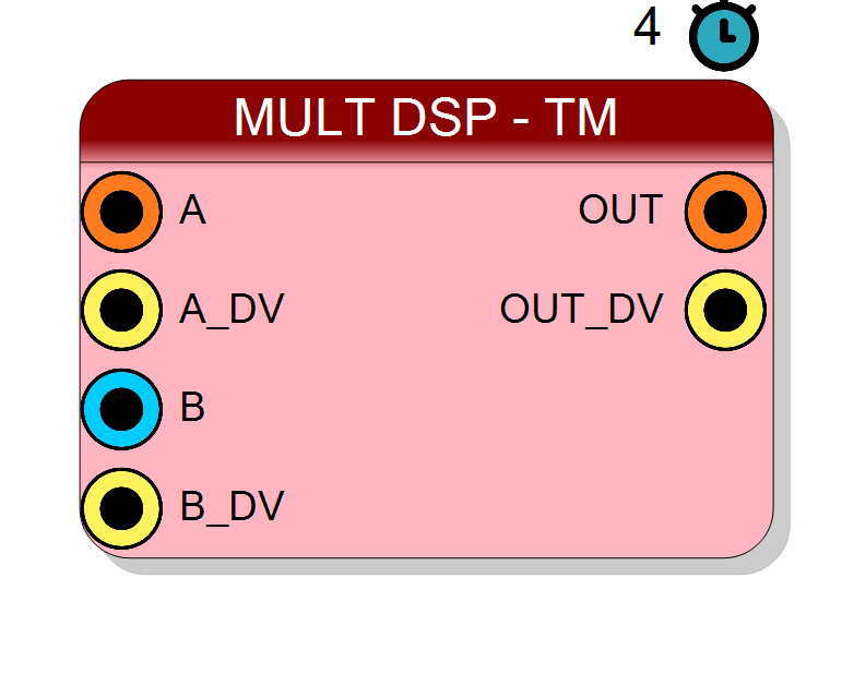
Introduction
The block performs time-multiplexed multiplication across multiple data streams. On every
rising edge of CLK, when A_DV = 1 and B_DV = 1, the multiplier computes
$$ \mathrm{OUT}_i(n) = \mathrm{A}_i(n) \times \mathrm{B}_i(n), \quad i = 0, \ldots, \text{TM}-1, $$
where each subscript $i$ represents a different TM phase, and TM is the time-multiplexing factor (4, 8, 16, or 32).
Input A is always time-multiplexed. Input B can be either time-multiplexed (performing
phase-by-phase multiplication) or scalar (multiplying all A phases by a single coefficient).
The component can leverage DSP48 slices for optimal performance or use LUT-based implementation for resource-constrained designs. Configurable pipeline stages (1-8) enable optimal timing closure at high clock frequencies.
Pin Description
Properties
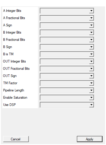
Number of integer bits for input A
Number of integer bits for input A. Range: 1-64. Default: 16. Determines the integer range of input A values.Default: 16
Options: 1 2 3 4 5 6 7 8 9 10 11 12 13 14 15 16 17 18 19 20 21 22 23 24 25 26 27 28 29 30 31 32 33 34 35 36 37 38 39 40 41 42 43 44 45 46 47 48 49 50 51 52 53 54 55 56 57 58 59 60 61 62 63 64
Number of fractional bits for input A
Number of fractional bits for input A. Range: 0-64. Default: 0. For Q16.0 format (16-bit integer), set to 0. For Q8.8 format, set to 8.Default: 0
Options: 0 1 2 3 4 5 6 7 8 9 10 11 12 13 14 15 16 17 18 19 20 21 22 23 24 25 26 27 28 29 30 31 32 33 34 35 36 37 38 39 40 41 42 43 44 45 46 47 48 49 50 51 52 53 54 55 56 57 58 59 60 61 62 63 64
Select if input A is signed or unsigned
Arithmetic type for input A:
- UNSIGNED → Range: [0, 2^(total_bits) - 1]
- SIGNED → Range: [-2^(total_bits-1), 2^(total_bits-1) - 1] Default: SIGNED
Default: SIGNED
Options: UNSIGNED SIGNED
Number of integer bits for input B
Number of integer bits for input B. Range: 1-64. Default: 16.Default: 16
Options: 1 2 3 4 5 6 7 8 9 10 11 12 13 14 15 16 17 18 19 20 21 22 23 24 25 26 27 28 29 30 31 32 33 34 35 36 37 38 39 40 41 42 43 44 45 46 47 48 49 50 51 52 53 54 55 56 57 58 59 60 61 62 63 64
Number of fractional bits for input B
Number of fractional bits for input B. Range: 0-64. Default: 0.Default: 0
Options: 0 1 2 3 4 5 6 7 8 9 10 11 12 13 14 15 16 17 18 19 20 21 22 23 24 25 26 27 28 29 30 31 32 33 34 35 36 37 38 39 40 41 42 43 44 45 46 47 48 49 50 51 52 53 54 55 56 57 58 59 60 61 62 63 64
Select if input B is signed or unsigned
Arithmetic type for input B:
- UNSIGNED → Non-negative values only
- SIGNED → Two’s complement representation Default: SIGNED
Default: SIGNED
Options: UNSIGNED SIGNED
Select if input B is Time Multiplexed or scalar
Determines if input B is time-multiplexed:
- NO → B is scalar coefficient, multiplied with all TM phases
- YES → B is TM, phase-by-phase multiplication with A Default: NO
Default: NO
Options: NO YES
Number of integer bits for output (typically sum of A+B integer bits)
Number of integer bits for output. Range: 1-64. Default: 32. For full precision, set to (A_BitsInt + B_BitsInt).Default: 32
Options: 1 2 3 4 5 6 7 8 9 10 11 12 13 14 15 16 17 18 19 20 21 22 23 24 25 26 27 28 29 30 31 32 33 34 35 36 37 38 39 40 41 42 43 44 45 46 47 48 49 50 51 52 53 54 55 56 57 58 59 60 61 62 63 64
Number of fractional bits for output (typically sum of A+B fractional bits)
Number of fractional bits for output. Range: 0-64. Default: 0. For full precision, set to (A_BitsFract + B_BitsFract).Default: 0
Options: 0 1 2 3 4 5 6 7 8 9 10 11 12 13 14 15 16 17 18 19 20 21 22 23 24 25 26 27 28 29 30 31 32 33 34 35 36 37 38 39 40 41 42 43 44 45 46 47 48 49 50 51 52 53 54 55 56 57 58 59 60 61 62 63 64
Select if output is signed or unsigned
Arithmetic type for output:
- UNSIGNED → Output range [0, 2^N - 1]
- SIGNED → Output range [-2^(N-1), 2^(N-1) - 1] Default: SIGNED
Default: SIGNED
Options: UNSIGNED SIGNED
Time Multiplexing factor
Time multiplexing factor (number of parallel phases). Values: 4, 8, 16, 32. Default: 4. Determines how many independent multiplications share the hardware.Default: 4
Options: 4 8 16 32
Number of pipeline stages (1-8)
Number of pipeline stages in the multiplier datapath. Range: 1-8. Default: 4. Higher values increase Fmax at the cost of latency. Total latency = PipelineLength × TM clock cycles.Default: 4
Options: 1 2 3 4 5 6 7 8
Enable output saturation (otherwise overflow)
Controls overflow behavior:
- YES → Saturate at maximum/minimum representable value
- NO → Wrap-around (modulo 2^N arithmetic) Default: YES.
Saturation prevents catastrophic errors in DSP chains.
Default: YES
Options: NO YES
Use DSP blocks for multiplication (otherwise LUT)
Selects multiplication implementation:
- YES → Use DSP48 slices (faster, lower power, limited resources)
- NO → Use LUT-based logic (slower, more area, unlimited) Default: YES.
Choose LUT-based for small multiplications or when DSP resources are exhausted.
Default: YES
Options: NO YES
Functional description
The component implements a time-multiplexed multiplier supporting independent fixed-point formats for each input:
$$ \text{OUT}[i] = A[i] \times B \quad \text{or} \quad \text{OUT}[i] = A[i] \times B[i], $$
where:
A[i]→ input A, phase $i$ (always TM)BorB[i]→ input B, scalar or TM phase $i$OUT[i]→ output, phase $i$ (always TM)
Each input has independently configurable:
- Integer bits (1-64)
- Fractional bits (0-64)
- Sign mode (SIGNED/UNSIGNED)
Mathematical background
In fixed-point arithmetic, multiplication of two Q-format numbers requires careful handling of the fractional point:
$$ \text{Q}{N_A.F_A} \times \text{Q}{N_B.F_B} = \text{Q}_{(N_A+N_B).(F_A+F_B)} $$
The natural output width is $(N_A + F_A) + (N_B + F_B)$ bits. The component scales and truncates/rounds the result to the configured output format.
For example, multiplying 16.0 × 16.0 fixed-point numbers produces a 32.0 result before scaling to the output format.
Time Multiplexing
Time multiplexing processes multiple independent multiplications through shared hardware:
| Clock cycle | Processing phase |
|---|---|
| 0 | Phase 0 → OUT[0] = A[0] × B[0] |
| 1 | Phase 1 → OUT[1] = A[1] × B[1] |
| … | … |
| TM-1 | Phase TM-1 → OUT[TM-1] = A[TM-1] × B[TM-1] |
| TM | Phase 0 (next cycle) |
Scalar Coefficient Mode
When B is TM = NO, input B acts as a scalar coefficient applied to all phases:
OUT[0] = A[0] × B
OUT[1] = A[1] × B
...
OUT[TM-1] = A[TM-1] × B
This is useful for:
- Gain/scaling operations
- Channel normalization
- Filter coefficient multiplication
DSP48 Slice Architecture
Xilinx DSP48 slices are specialized blocks containing:
- 25×18-bit multiplier
- 48-bit accumulator/ALU
- Pre-adder for filter efficiency
- Cascade paths for wide arithmetic
The Use DSP property allows choosing between:
- YES → Use DSP48 slices (faster, lower power, limited quantity)
- NO → Use LUT-based multiplication (slower, more fabric, unlimited quantity)
Overflow Handling
The Enable Saturation property controls overflow behavior:
- YES → Output saturates at maximum/minimum representable value
- NO → Output wraps around (modulo arithmetic)
Saturation prevents catastrophic errors in DSP chains but adds logic overhead.
Pipeline and Timing
The Pipeline Length property (1-8 stages) controls latency versus maximum clock frequency:
| Pipeline Length | Latency (clock cycles) | Typical Fmax improvement |
|---|---|---|
| 1 | TM × 1 | Baseline |
| 2 | TM × 2 | +25% |
| 3 | TM × 3 | +40% |
| 4 | TM × 4 | +50% |
| 8 | TM × 8 | +65% |
Deeper pipelines enable higher clock rates, critical for wideband signal processing.
Resource Utilization
Typical resource usage (TM=4, 16×16 multiplication):
| Implementation | DSP48 | LUTs | FFs | Fmax (typical) |
|---|---|---|---|---|
| DSP-based | 1 | ~50 | ~100 | 600+ MHz |
| LUT-based | 0 | ~400 | ~200 | 350-450 MHz |
Typical use cases
- FIR filter coefficient multiplication
- Gain control in multi-channel audio/video
- Complex number multiplication (I/Q processing)
- Scaling in fixed-point neural networks
- Modulation/demodulation in SDR
- Matrix-vector multiplication
Waveform example
Example with TM=4, Pipeline=4, B is scalar gain: