
TDC 500ps Controller
Multi-phase clock generator and coarse time-base provider for 500 ps Time-to-Digital Converters. The block derives six phase-shifted clocks from a single 125 MHz reference and delivers them, together with a user-programmable coarse counter, on a unified management bus.
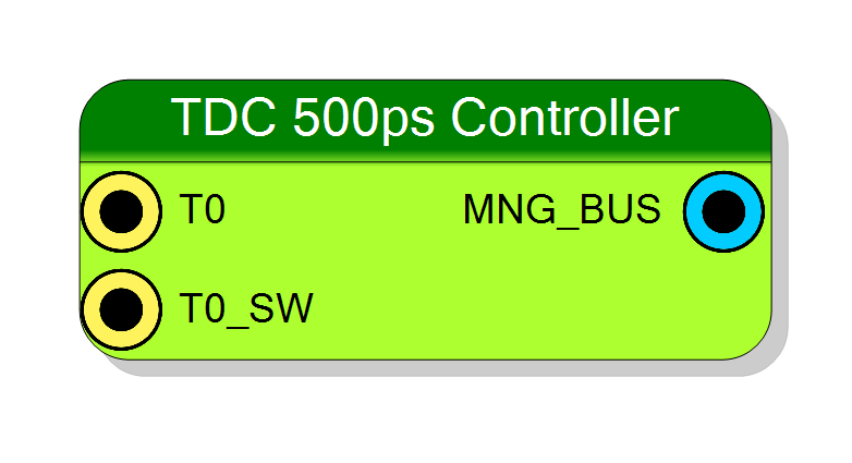
Introduction
The TDC 500 ps Controller (entity TDC_8PHASE_CNTRL) is the clock-generation and coarse-time backbone for Sci-Compiler 8-phase TDC slices.
A mixed-mode PLL converts an incoming 125 MHz reference into two quadrature clocks at 125 MHz and four equi-spaced clocks at 250 MHz, enabling an effective 8-phase interpolation:
$$ T_{fine}=\frac{T_{clk125}}{16}=\frac{1}{125,\text{MHz}\times16}=0.5,\text{ns} $$
Together with a free-running coarse counter, the block extends the measurable interval to $2^{N},\times8,\text{ns}$ (where $N$ is CoarseBits).
graph TD
ref[125 MHz REF CLK] -->|PLL| C1(125 MHz 0°)
ref -->|PLL| C2(125 MHz 90°)
ref -->|PLL| C3(250 MHz 0°)
ref -->|PLL| C4(250 MHz 90°)
ref -->|PLL| C5(250 MHz 180°)
ref -->|PLL| C6(250 MHz 270°)
C1 --> Cntr[Coarse Counter]
C1 -.-> Bus[MNG_BUS]
C2 -.-> Bus[MNG_BUS]
C3 -.-> Bus[MNG_BUS]
C4 -.-> Bus[MNG_BUS]
C5 -.-> Bus[MNG_BUS]
C6 -.-> Bus[MNG_BUS]
Cntr -.-> Bus[MNG_BUS]
Pin Description
MNG_BUS[CoarseBits+7]. When ResetOnT0 is enabled the same edge clears the coarse counter after a four-cycle debounce window.
CLK125_0. This signal can be connected to a register
Properties
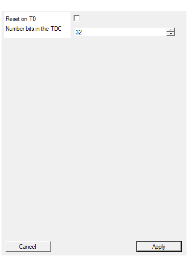
Reset coarse on T0
If true, the coarse counter is automatically cleared on every hit (T0). The reset is asserted for four cycles ofCLK125_0 (≈32 ns) to guarantee metastability-free operation. If false, the counter runs continuously and can only be reset through T0_SW or GlobalReset.
Default: False
This module generate the coarse. This parameter must be matched with the Coarse Bit parameter of each controlled TDC
Width N of the coarse counter (1‥256). Determines both the dynamic range ($2^{N}\times8,\text{ns}$) and the overall width ofMNG_BUS. All controlled TDC slices must use the same value.
Default: 32
Usage
The controller performs three main functions:
-
Phase-aligned clock generation
A Xilinx PLL (TDC_05NS_PLL) produces six clocks:•
CLK125_0– 125 MHz @0°
•CLK125_90– 125 MHz @90°
•CLK250_0– 250 MHz @0°
•CLK250_90– 250 MHz @90°
•CLK250_180– 250 MHz @180°
•CLK250_270– 250 MHz @270°
The full-speed group (250 MHz) provides four equidistant sampling points, while the quadrature 125 MHz clocks double the available phases, resulting in an overall fine resolution of 500 ps. -
Coarse counter
A synchronous binary counter driven byCLK125_0delivers the coarse time word $c$ (width = CoarseBits).
The optional reset on each hit is controlled by property ResetOnT0. -
Unified management bus
All clocks, the coarse word and status flags are packed intoMNG_BUS(width = CoarseBits + 8):Bit index Symbol Description 0 CLK125_0 125 MHz @0° 1 CLK125_90 125 MHz @90° 2 CLK250_0 250 MHz @0° 3 CLK250_90 250 MHz @90° 4 CLK250_180 250 MHz @180° 5 CLK250_270 250 MHz @270° 6‥6+N-1 COARSE[N-1:0] Free-running coarse counter 6+N G_RESET Synchronous copy of GlobalReset 7+N HIT_FLAG Synchronous copy of T0 where $N=$ CoarseBits.
Mathematical model
The reconstructed time stamp is obtained as $$ t_{meas}=c,T_{coarse}+f,T_{fine} $$ with $T_{coarse}=8,\text{ns}$ and $T_{fine}=0.5,\text{ns}$.
Timing
• Clock-to-out of the PLL: <100 ps (device-dependent).
• Coarse counter latency: 1 cycle of CLK125_0 (8 ns) from rising edge to availability on MNG_BUS.
Typical application: use several fine TDC slices to digitise leading-edge hits at 500 ps LSB while maintaining up to $2^{32} \times 8,\text{ns}\approx34,\text{s}$ dynamic range.