
Min Detector
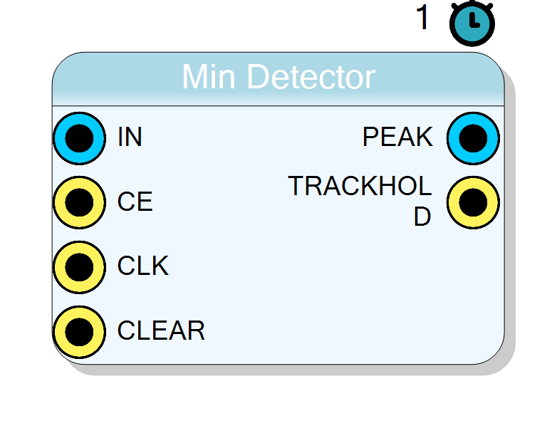
Digital minimum-holder. The block continuously tracks the lowest (most negative) value observed on the DATA_IN bus and keeps it at the output until a new, even lower sample is detected. A single synchronous clock cycle of latency is introduced between the accepted sample and its appearance on DATA_OUT.
Introduction
The Min Detector captures the minimum value of a signed or unsigned
sample stream.
On every rising edge of CLK, when CE is asserted, the incoming sample
DATA_IN is compared with the internal register PEAK.
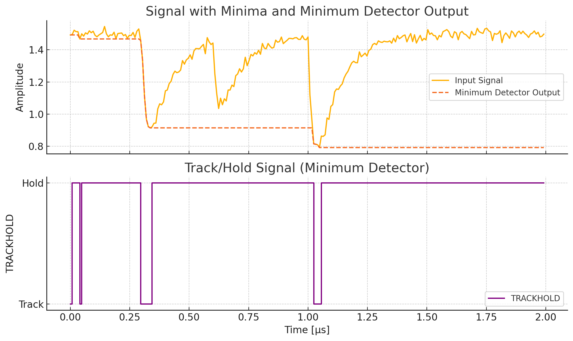
• If DATA_IN < PEAK the new minimum is stored and the block is in
tracking mode (TRACKHOLD = '0').
• Otherwise the previous minimum is held (TRACKHOLD = '1').
A global asynchronous RESET initializes the stored minimum to the highest
possible code (all 1’s), guaranteeing the very first valid sample is always
accepted.
Pin Description
Width set by
WordWidth.Sample is evaluated on every rising edge of
CLK only when CE = 1.
When 1 the current
DATA_IN value participates in the minimum
comparison; when 0 the internal register and TRACKHOLD remain
unchanged.
All synchronous behaviour of the block is referenced to this signal.
Forces the stored minimum to all 1’s and clears
TRACKHOLD.Must be asserted for at least one clock period.
Valid one clock cycle after the corresponding input sample has been accepted.
•
0 – tracking (a new minimum was captured this cycle)•
1 – hold (no update, output unchanged)
Properties
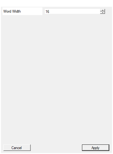
Width of the input data in bits
Width ofDATA_IN and DATA_OUT buses in bits.Range : 4 – 32
• Larger width increases comparator size and register footprint.
• Does not alter latency or interface timing.
Default: 16
Range: 4 – 32
Functional principle
Let x[n] be the input sample at clock cycle n and
m[n] the value available on DATA_OUT at the same instant.
The behaviour can be expressed as
$$ m[n+1] = \begin{cases} \min\bigl(m[n],,x[n]\bigr) & \text{if } CE = 1 \[4pt] m[n] & \text{if } CE = 0 \end{cases} $$
with the initial condition
$$ m[0] = 2^{\texttt{WordWidth}} - 1 $$
The signal TRACKHOLD flags the operating state:
$$ TRACKHOLD = \begin{cases} 0 & \text{tracking (new minimum stored)}\ 1 & \text{hold (no update)} \end{cases} $$
Timing
• Clock domain CLK – rising edge triggered
• Latency 1 clock cycle.
The sample accepted at cycle n appears on DATA_OUT at cycle n + 1.
• Asynchronous reset RESET active-high, clears the internal register in
the same cycle it is asserted.
Typical applications
- Minimum sensing in spectroscopy pipelines (e.g. baseline search)
- Envelope detection of negative-going pulses
- Digital implementation of sample-and-hold for valley detection