Smart Connect & Automatic Signal Conversion
Connect whole groups of pins in a few clicks: the Smart Connect mapping window with pattern-based Auto map, the click-click Link mode (L key), and the automatic insertion of size and time-multiplexing conversion blocks when the two ends of a net do not match.
Smart Connect
Smart connect is available in the Connection section of the diagram right-click menu and on the L key. What it does depends on the current pin selection:
| Selection | Behaviour |
|---|---|
| Nothing selected | Enters Link mode (see below) |
| One pin | Enters Link mode with that pin already armed: click the destination pin to wire |
| One pin per block on two blocks | The net is created immediately, no window |
| Several pins on ONE block | The cursor becomes a picker: click the target block to open the mapping window on all its pins |
| Pins selected on TWO blocks | The mapping window opens restricted to the selected pins only |
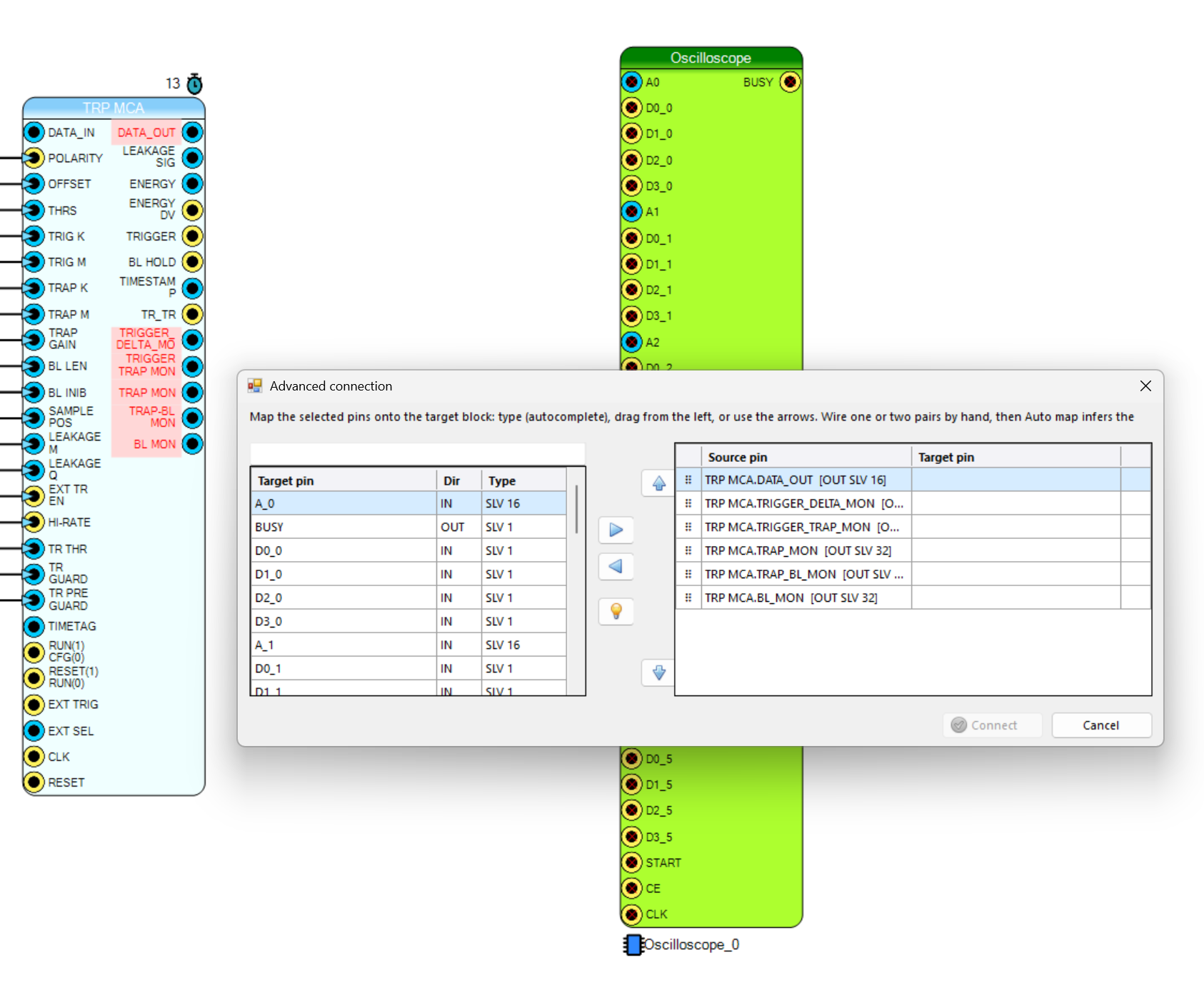
Figure 1: the Smart connect mapping window
The mapping window
Target pins with a search box on the left, one row per source pin on the right. Pairs can be defined by typing (autocomplete), dragging target pins onto the rows, or with the center arrows; rows reorder with the ⠿ handle or the up/down buttons, and after each association the focus moves to the next row. Direction is resolved automatically (output → input, whatever side each pin is on).
Every pair is checked live:
- ✔ green — compatible.
- ⚠ yellow — sizes or TM do not match, but the enabled automatic conversion will fix it: the tooltip explains what will be inserted. Yellow pairs do not block the connection.
- ✘ red — incompatible (blocks the Connect button; the tooltip explains why).
Auto map
Wire one or two pairs by hand, then press the Auto map (bulb) button: the editor learns the naming pattern and proposes the remaining pairs. The inference is deterministic and works offline:
- Name patterns: from
ENERGY_0 → DATA_1it learnsENERGY_# → DATA_#with offset +1, soENERGY_1 → DATA_2,ENERGY_2 → DATA_3, … A second example with a different index upgrades the offset to a full linear fit. - Row position: when the names share nothing (
TRIGGER_DELTA_MON → A_0), the row position drives the index: the next rows are proposed onA_1,A_2, … Reordering the rows before pressing Auto map redefines the sequence. - Typo tolerant:
ENRGY_1still matches theENERGY_#rule.
Suggested pairs are shown in azure with a bulb icon and the applied rule in the tooltip;
editing a suggested row confirms it, the < arrow clears it.
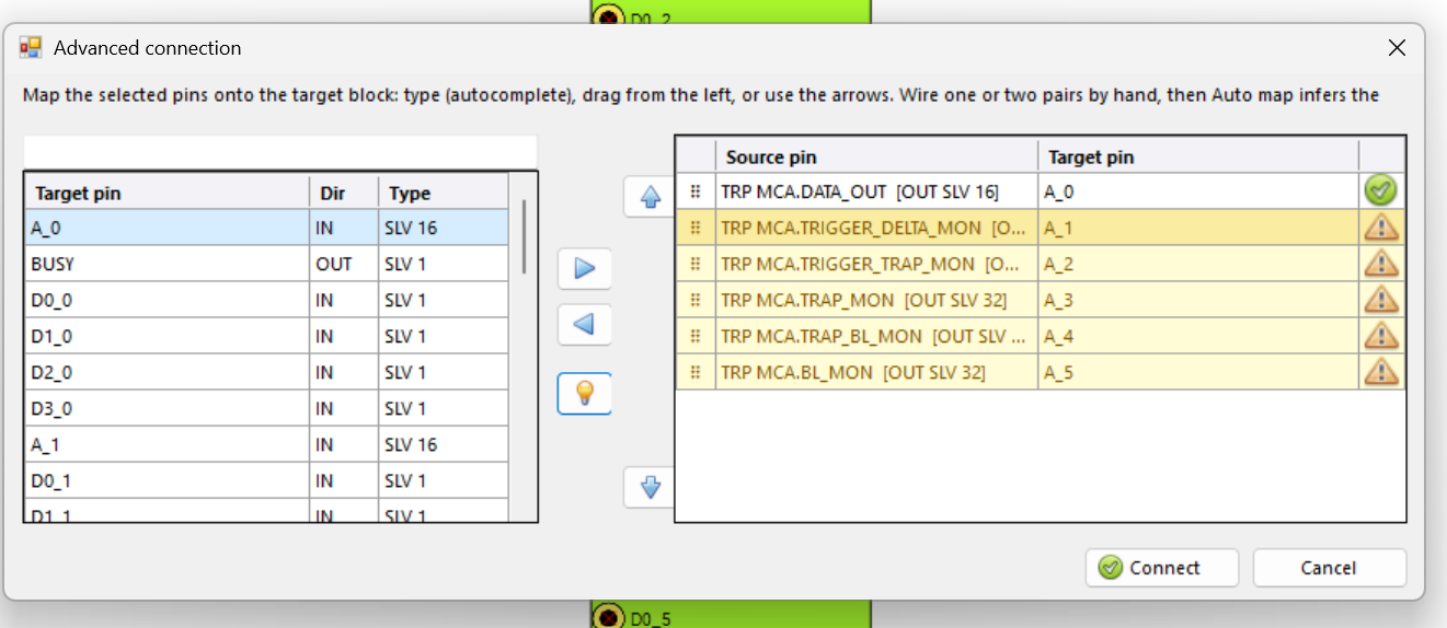
Figure 2: Auto map fills the remaining rows from one manual example
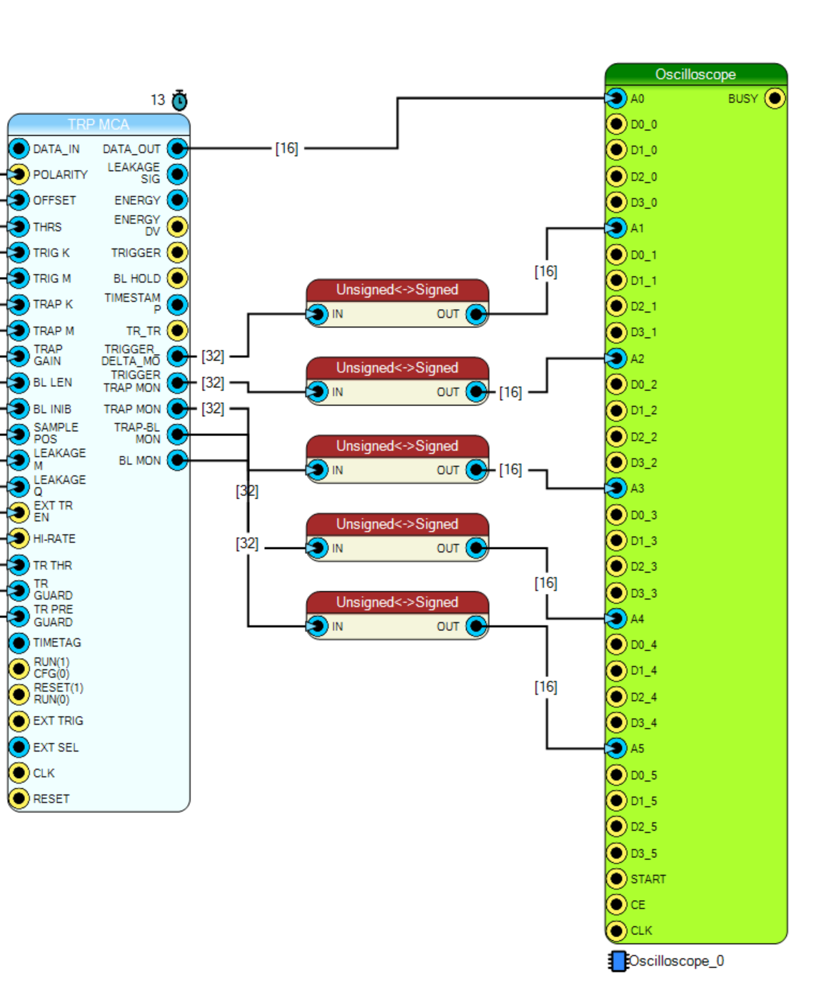
Figure 3: the result on the diagram — the monitor outputs reach the oscilloscope channels, and where the sizes did not match (32 → 16 bit) an Unsigned<->Signed converter has been inserted and wired automatically
Link Mode (L)
Press L with nothing selected: the cursor becomes an arrow with a link symbol and a toast bar explains what to do. Click the first pin (it gets armed), then the second pin — in any order, the direction is resolved automatically — and the net is created. The mode stays active so more nets can be chained; it ends only with a right click or by pressing L again.
If the two pins do not match in size or TM, the enabled automatic conversion inserts the proper adapter (see below).
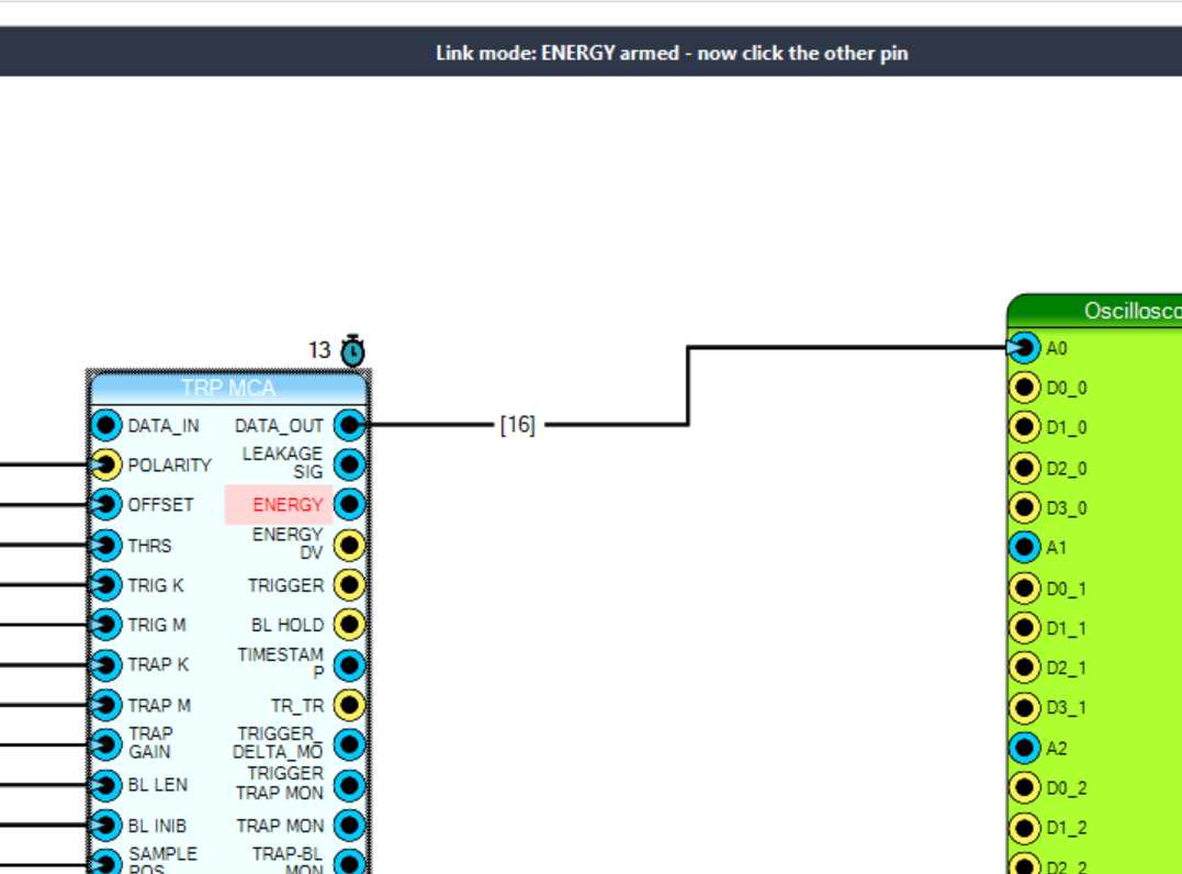
Figure 4: link mode cursor and toast
Automatic Signal Conversion
Drawing a net between two pins of the same type but different bit size normally fails with a size-mismatch error. With automatic conversion enabled, the editor inserts an Unsigned<->Signed converter (or its TM twin) between source and destination, with the two sizes pre-configured, and wires both sides.
The behaviour is selected from the Signal conversion picker, available in the Editor ribbon group and in the Connection section of the right-click menu:
| Mode | Behaviour |
|---|---|
| Ask (default) | Opens the converter dialog pre-configured with the two sizes: choose the signs and confirm |
| Signed → Signed | Inserted silently, both sides signed |
| Unsigned → Unsigned | Inserted silently, both sides unsigned |
| Signed → Unsigned | Input signed, output unsigned |
| Unsigned → Signed | Input unsigned, output signed |
| Disabled | Standard error message |
TM Adaptation
Similarly, connecting a plain signal to a time-multiplexed pin inserts a TM Signal Replicator, and a TM signal to a plain pin a TM Phase Extractor (phase 0 by default). The TM adaptation picker offers Ask (dialog pre-configured), Enabled (silent) and Disabled. Sizes must match on the two sides.
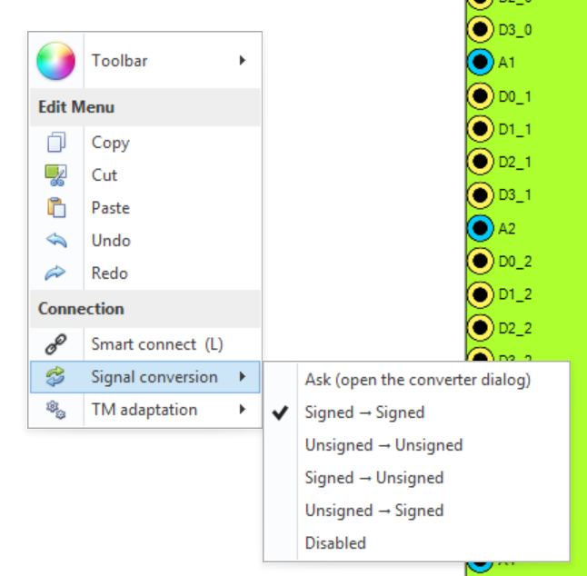
Figure 5: the Signal conversion and TM adaptation pickers
Both settings are saved per SCI-Compiler installation (not in the project) and apply to manually drawn nets, to Link mode and to the Smart connect window.
Shortcuts Recap
| Key | Action |
|---|---|
| L | Smart connect on the current pin selection / Link mode toggle |
| Ctrl + click on pin | Add / remove pin from the selection |
| Shift + click on pin | Range selection (start / end) |
| Right click | Exits Link mode and the pick modes |