
Trigger LE TM
Time-multiplexed leading-edge digital trigger with optional hysteresis, programmable dead-time inhibition and Time-over-Threshold (ToT) output. Generates trigger pulses when the input signal crosses programmable thresholds, with precise sub-clock-cycle timing resolution within the TM frame.
Introduction
The Trigger LE TM core implements a leading-edge discriminator optimized for time-multiplexed (TM) data streams, commonly used in high-speed nuclear and particle physics data-acquisition systems. The core processes TM_Factor parallel samples per clock cycle, detecting threshold crossings with sub-clock-cycle precision.
A key feature is the optional hysteresis mode, which uses two separate thresholds (high and low) to prevent false triggers caused by noise when the signal hovers near the threshold level.
Pin Description
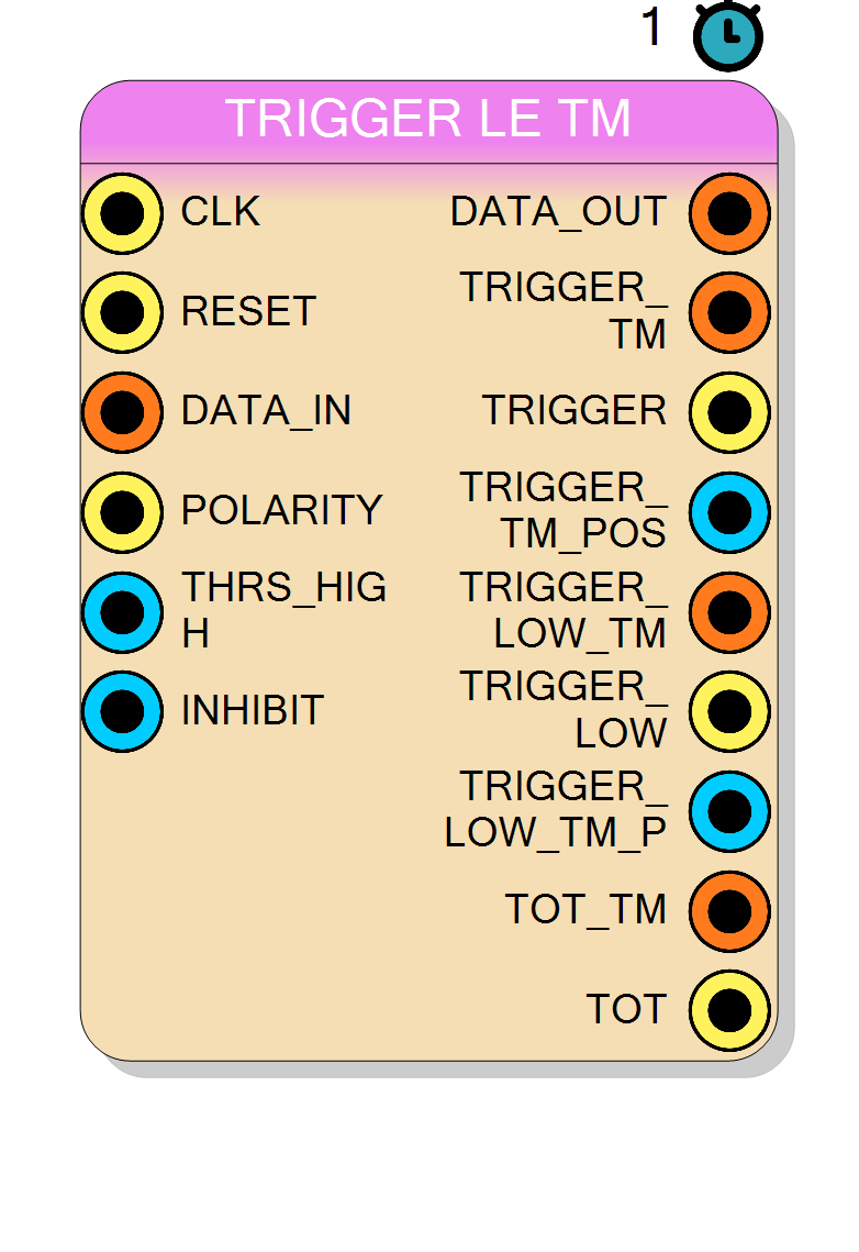
CLK.
Selects trigger edge polarity.
1– detect positive excursions (signal rising above threshold)0– detect negative excursions (signal falling below threshold) Width = 1 bit.
POLARITY.
TRIGGER_TM.
TRIGGER = 1.
THRS_LOW).
Each bit corresponds to one TM sample; bit i is set if sample i caused a trigger STOP.
Width equals TM_Factor bits.
TRIGGER_LOW_TM.
TRIGGER_LOW = 1.
THRS_HIGH.
Width equals TM_Factor bits.
TOT_TM. High when any TM sample is above threshold.
USE_HYSTERESIS = 1, a trigger STOP is generated when the signal falls below this level.
Should be set to THRS_LOW <= THRS_HIGH for correct operation.
Only visible when Hysteresis property is enabled.
Runtime enable for hysteresis mode.
1– Use separate high/low thresholds (hysteresis enabled)0– Use onlyTHRS_HIGH(hysteresis disabled) Only visible when Hysteresis property is enabled.
Properties
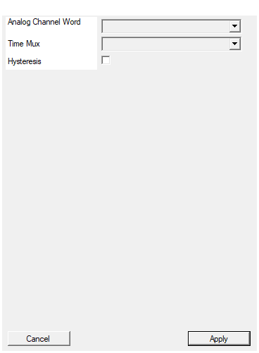
Set the analog channel word size in bits
Bit-width of each sample within the TM frame. Applies toDATA_IN, THRS_HIGH, THRS_LOW and DATA_OUT signals.
Available values: 16, 32, 64, default 16.
Note: This property is typically hidden and auto-configured based on the connected signal.
Default: 16
Options: 16 32 64
Set number of samples for each clock cycle
Number of parallel samples processed per clock cycle (TM_Factor). Determines the effective sampling rate multiplication and sub-clock timing resolution. Available values: 2, 4, 8, 16, 32, default 4.Default: 4
Options: 2 4 8 16 32
Enable hysteresis logic to separate L->H to H->L commutation
Enable hysteresis logic to use separate thresholds for trigger arming and disarming.
When enabled, the THRS_LOW and USE_HYSTERESIS inputs become available.
- False (default) – Single threshold mode
- True – Hysteresis mode with separate high/low thresholds
Default: False
Usage
Functional overview
The core compares each of the TM_Factor parallel input samples against the programmable threshold(s) and detects transitions:
Without hysteresis (USE_HYSTERESIS = 0):
- Single threshold
THRS_HIGHis used - Trigger START occurs when signal crosses
THRS_HIGH(low-to-high transition) - Trigger STOP occurs simultaneously with START (instantaneous pulse)
With hysteresis (USE_HYSTERESIS = 1):
- Two thresholds are used:
THRS_HIGHandTHRS_LOW(whereTHRS_LOW <= THRS_HIGH) - Trigger START occurs when signal crosses
THRS_HIGH(low-to-high transition) - Trigger STOP occurs when signal falls below
THRS_LOW(high-to-low transition) - The trigger remains “armed” only after the signal has fallen below
THRS_LOW
What is Hysteresis?
Hysteresis is a technique used to prevent spurious trigger events caused by noise when the signal amplitude is close to the threshold level. Without hysteresis, noise fluctuations can cause the signal to repeatedly cross the threshold, generating multiple false triggers from a single pulse.
With hysteresis enabled, two distinct thresholds are defined:
- THRS_HIGH: The signal must rise above this level to generate a trigger START
- THRS_LOW: The signal must fall below this level before the trigger can be re-armed
This creates a “dead zone” between the two thresholds where crossing events are ignored, effectively filtering out noise-induced oscillations.
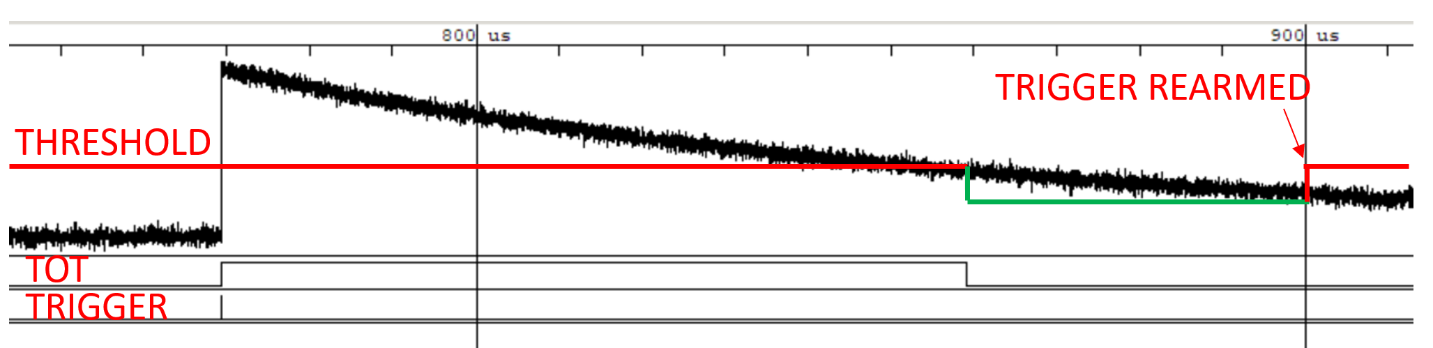
In the figure above:
- The red line shows the threshold level
- The green region indicates when the trigger is waiting to be re-armed (signal must fall below
THRS_LOW) - TRIGGER REARMED marks when the system is ready to accept a new trigger
- The TOT signal shows the Time-over-Threshold duration
- The TRIGGER pulse marks the leading edge detection
Polarity
The POLARITY input allows inverting the trigger logic:
POLARITY = 1(positive): Trigger on rising edges (signal going above threshold)POLARITY = 0(negative): Trigger on falling edges (signal going below threshold)
Dead-time Inhibition
After each trigger, new triggers can be inhibited for a programmable number of clock cycles using the INHIBIT input. This prevents re-triggering on the same pulse or on pile-up events.
The inhibition operates at the TM sample level, meaning the exact inhibition duration is: $$ t_{inhibit} = \text{INHIBIT} \times T_{clk} $$
where $T_{clk}$ is the clock period. The inhibition mask is applied precisely, ensuring consistent dead-time regardless of where within the TM frame the trigger occurred.
Time-over-Threshold (ToT)
The core provides ToT outputs that indicate how long the signal remains above the threshold. Two methods are available (selected at compile time via TOT_METHOD generic):
- Method 0 (Full): ToT starts with trigger START and ends when signal falls below
THRS_HIGH - Method 1 (Simple): ToT directly reflects whether the signal is above
THRS_HIGH
Time-multiplexed outputs
The core provides multiple trigger-related outputs with TM precision:
TRIGGER– single-bit pulse, asserted for one clock cycle when any TM channel triggersTRIGGER_TM– TM_Factor-bit vector indicating which specific TM sample triggeredTRIGGER_TM_POS– binary-encoded index of the first triggering TM sample
Similarly for the STOP event (when using hysteresis):
TRIGGER_LOW– single-bit pulse when signal falls belowTHRS_LOWTRIGGER_LOW_TM– TM vector for the low threshold crossingTRIGGER_LOW_TM_POS– binary index of the STOP event
Timing
- Threshold comparisons are performed combinatorially on the input data.
- Transition detection and trigger generation occur with 1 clock cycle latency.
DATA_OUTprovides a pass-through of the input data (no additional delay).
Typical applications
- Photon or particle counting with scintillators and SiPM/PMT front-ends
- Leading-edge discriminator with noise rejection via hysteresis
- Digital oscilloscope trigger with programmable dead-time
- Pulse width measurement using ToT outputs