
Monostable (Pulse Shaper)
Monostable multivibrator (one-shot) that generates fixed-width output pulses in response to input edges. Converts edge transitions into precisely-timed pulses with configurable width and delay. Supports both rising and falling edge triggering, with optional zero-delay combinational mode. Essential for creating timing strobes, pulse standardization, and event acknowledgment signals.
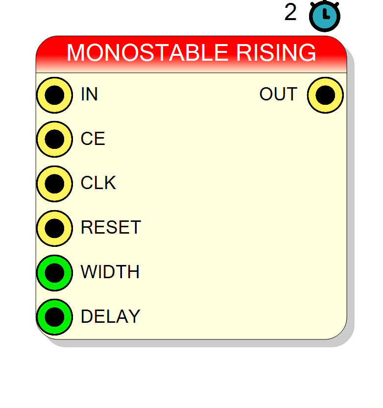
Introduction
This block implements a monostable multivibrator (also called a pulse shaper or one-shot) that generates output pulses of fixed width when triggered by input edges.
The monostable operates as follows:
- Detects edges on the input signal (rising or falling, configurable)
- Generates an output pulse of precisely controlled width
- Optional delay before pulse starts
- Optional zero-delay mode for combinational pulse generation
Key characteristics:
- Edge-triggered: Responds to input transitions
- Fixed pulse width: Configurable from 1 to N clock cycles
- Configurable delay: Optional delay before pulse generation
- Zero-delay mode: Combinational logic option (no latency)
- Latency: 2 + DELAY clock cycles (0 in zero-delay mode)
- Asynchronous input allowed in normal mode: the input crosses two register stages before the edge is detected
Pin Description
Clock Enable input (active high).
- CE = ‘1’: Monostable enabled, can be triggered
- CE = ‘0’: Monostable disabled, triggers ignored Default: ‘1’ if left unconnected.
Pulse width in clock cycles (integer). Determines how many cycles the output pulse remains high.
- WIDTH = 1: Single-cycle pulse
- WIDTH = N: N-cycle pulse Default: 1 if left unconnected.
Delay in clock cycles before pulse starts (integer).
- DELAY = 0: Pulse starts immediately after edge detection
- DELAY = N: Pulse starts N cycles after edge detection Must be 0 when NoDelay = TRUE. Default: 0 if left unconnected.
Properties
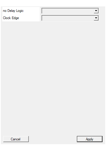
Add combination logic to reduce the delay to 0 (delay must be set to 0 also)
Enable zero-delay combinational mode: TRUE (combinational, DELAY must be 0) or FALSE (clocked, default). Use TRUE only when zero latency is critical.Default: FALSE
Options: TRUE FALSE
Select between rising and falling edge
Trigger edge polarity: RISING (trigger on 0→1 transitions) or FALLING (trigger on 1→0 transitions).Default: RISING
Options: RISING FALLING
Functional description
A monostable multivibrator is a pulse-generating circuit that produces a single output pulse of fixed duration in response to an input trigger. Unlike bistable flip-flops, monostables return to their stable state after a defined time.
Operation modes
The component has two operational modes:
Normal mode (NoDelay = FALSE)
- Registers the input through two register stages, then detects the edge between them. The first stage resynchronizes the input, so the input may be asynchronous with respect to the clock
- Generates pulse after configurable delay
- Latency: 2 + DELAY clock cycles (2 = the two input register stages)
- Output pulse width = WIDTH cycles, whatever the length of the input pulse
Zero-delay mode (NoDelay = TRUE)
- Combinational logic implementation
- Instant edge detection
- DELAY parameter must be set to 0
- Latency: 0 clock cycles (combinational)
- Pulse appears immediately (same cycle as edge)
- Output pulse width = WIDTH cycles, whatever the length of the input pulse
- Because the output is combinational there is no resynchronization stage: in this mode the input must already be synchronous with the clock
Edge detection
The Edge property selects trigger polarity:
- RISING: Triggers on 0→1 transitions
- FALLING: Triggers on 1→0 transitions
Timing parameters
Three parameters control pulse timing:
-
DELAY (clock cycles):
- Delay from edge detection to pulse start
- DELAY = 0: Pulse starts immediately
- DELAY = N: Pulse starts N cycles after edge
-
WIDTH (clock cycles):
- Duration of the output pulse
- WIDTH = 1: Single-cycle pulse
- WIDTH = N: N-cycle pulse
-
NoDelay (property):
- FALSE: Normal clocked operation
- TRUE: Combinational zero-latency mode
Pulse generation timing
In normal mode:
Cycle: 0 1 2 3 4 5 6 7
IN: 0 1 1 1 1 1 1 1 (rising edge at cycle 1)
OUT: 0 0 0 0 1 1 0 0 (DELAY=1, WIDTH=2)
^ 2 cycles ^pulse^
^ + DELAY ^
In zero-delay mode (NoDelay=TRUE, DELAY=0):
Cycle: 0 1 2 3 4
IN: 0 1 1 1 1 (rising edge at cycle 1)
OUT: 0 1 1 0 0 (WIDTH=2, instant response)
^pulse^
Retriggerable behavior
If a new edge arrives during an ongoing pulse:
- Behavior depends on implementation
- Typically: pulse restarts (retriggerable)
- Use CE to disable during active pulse for non-retriggerable
Timing
| Mode | Latency (clock cycles) | Input |
|---|---|---|
| Normal | 2 + DELAY | may be asynchronous |
| Zero-delay | 0 (combinational) | must be synchronous |
Typical use cases
- Pulse standardization: Convert variable-width inputs to fixed pulses
- Strobe generation: Create precise timing strobes for data capture
- Debouncing: Generate clean pulses from noisy button inputs
- Acknowledge signals: Create fixed-width ack pulses
- Timeout generation: Monostable timers for watchdog circuits
- Interrupt pulse shaping: Standardize interrupt signal widths
- Protocol timing: Generate protocol-compliant pulse widths
- One-shot triggers: Single-pulse generation for control logic
Design best practices
- Zero-delay mode: Use only when zero latency is critical
- Width selection: Match WIDTH to downstream requirements
- Delay usage: Use DELAY for precise timing alignment
- Retriggering: Consider whether retriggerable behavior is desired
- CE control: Use CE to prevent unwanted retriggering
Waveform examples
Normal mode (NoDelay = FALSE)
DELAY = 2, WIDTH = 3, Edge = RISING:
The edge is at cycle 2, the pulse starts at cycle 6 (2 input register stages
- DELAY = 2) and lasts 3 cycles (WIDTH).
Zero-delay mode (NoDelay = TRUE)
DELAY = 0, WIDTH = 2, Edge = RISING:
Pulse appears immediately (combinational), lasts 2 cycles.
Falling edge trigger
DELAY = 0, WIDTH = 1, Edge = FALLING, NoDelay = FALSE:
Single-cycle pulses, 2 cycles after each falling edge.