
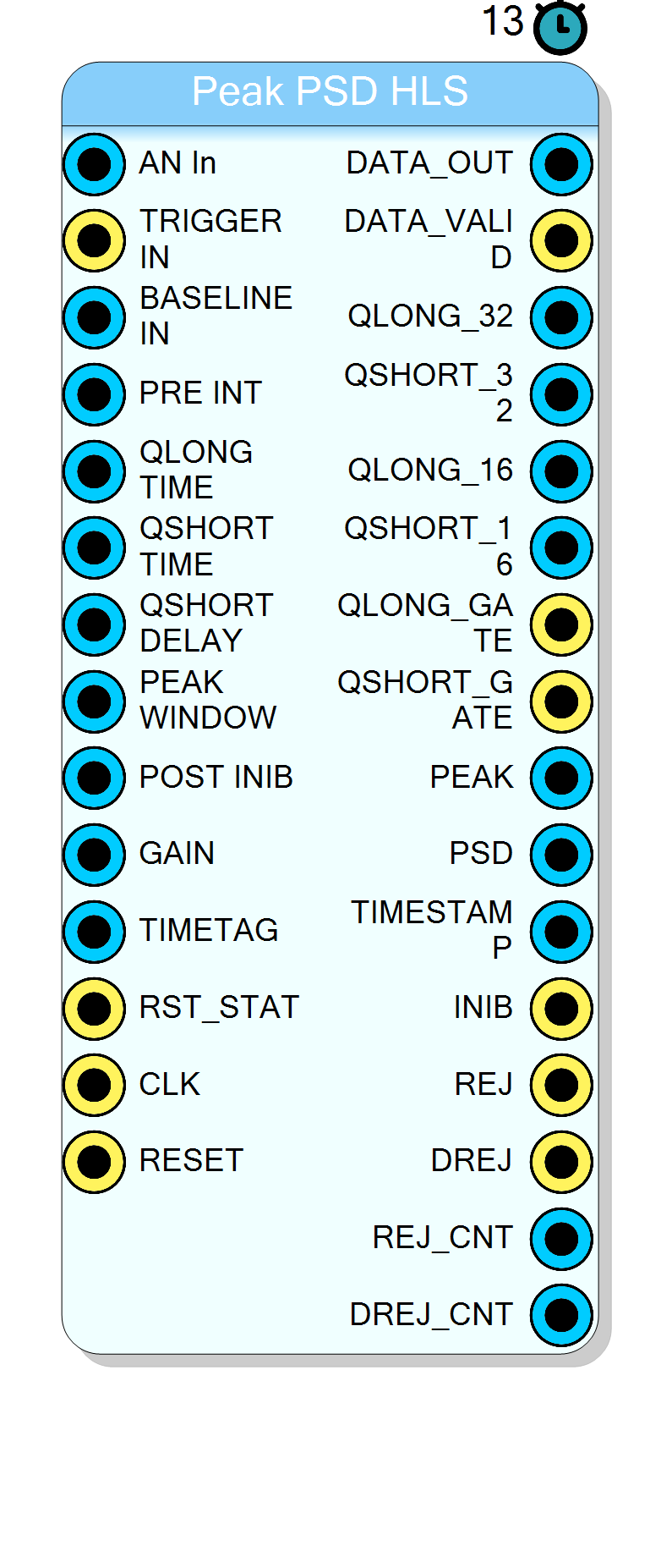
Peak PSD HLS
Charge integration (QDC) with peak detection and a Pulse Shape Discrimination ratio built from the pulse AMPLITUDE over the charge of a delayed gate. Unlike the standard QDC/PSD block, whose ratio compares two charges, this block divides the peak height by Qshort, which makes the discrimination insensitive to the total collected charge. Paralysable pile-up rejection with separate counters for the two rejection causes.
Introduction
The Peak PSD HLS block integrates the charge of a pulse over two gates, measures the peak amplitude of the same pulse, and forms a discrimination ratio as
$$ \mathrm{PSD} = \frac{\mathrm{PEAK}}{Q_{short}} $$
This is what separates it from the QDC/PSD HLS block, where the ratio is formed between two charges. Here the numerator is the height of the pulse and the denominator is the charge of a gate that can be delayed with respect to the trigger, so the ratio compares the prompt amplitude against the charge of the tail.
The block provides, for every accepted event:
- Qlong: charge integrated over the long gate, raw (32 bit) and scaled (16 bit)
- Qshort: charge integrated over the delayed short gate, raw and scaled
- PEAK: the maximum sample of the pulse, baseline subtracted
- PSD: the peak-over-Qshort ratio in fixed point
- TIMESTAMP: the value of
TIMETAGlatched at the end of the long gate
The core is written in Xilinx HLS and runs at II = 1: it accepts one sample per clock and never back-pressures.
Pin Description
INIB is high is counted as a rejection.
0 bypasses the delay line and works on the live sample.
Must stay below 256, the depth of the delay line.
Typical values: 5 to 50 samples, enough to contain the leading edge of the pulse.
QSHORT DELAY it selects which part of the pulse ends up in the
denominator of the PSD ratio.
0 makes the short gate a prompt gate; a non zero value makes it a tail gate that
skips the leading edge.
Declared stable in the HLS core: do not change it while the block is acquiring.
REJ and reloads the full dead time.
Q16 = (Q32 * GAIN) >> 16.
65535 is approximately unity gain, 32768 halves, 6554 divides by ten.
The result saturates at 65535 and is clamped to 0 when the charge is negative.
TIMESTAMP. Connect it to a Timestamp Generator block.
REJ_CNT and DREJ_CNT.
The measurement itself is not affected.
PRE INT. Probe it to verify baseline and pre-trigger before trusting the charges.
DATA_VALID.
QLONG_32.
It is the denominator of the PSD ratio.
GAIN and saturated to 16 bits, latched at the end of the
gate. Meant to feed a spectrum block directly.
GAIN and saturated to 16 bits, latched at the end of the
gate.
QSHORT DELAY and for QSHORT TIME samples.
PEAK WINDOW, latched at the end of
the long gate and held until the next accepted event.
PEAK / Qshort in fixed point with 16 fractional bits:
divide by 65536 to read it as a real number.
Forced to 0 when Qshort is zero or negative.
TIMETAG latched at the end of the long gate, 64 bits.
REJ pulses. Cleared by RST_STAT.
DREJ pulses, that is of the events lost to double
pulses. Compare it with the accepted count to estimate the pile-up fraction.
Cleared by RST_STAT.
Functional description
Baseline subtraction and pre-trigger
Every incoming sample is baseline subtracted first, on 17 signed bits, so a sample below the baseline stays negative instead of wrapping:
sample = AN_In - BASELINE_In
The result goes into a 256-position delay line. PRE INT selects how far back the
block reads from that line, which is what lets every gate start before the trigger
arrives and capture the leading edge of the pulse. With PRE INT = 0 the delay line is
bypassed entirely and the block works on the live sample.
The delay line is 256 deep:
PRE INTmust stay below 256. A larger value wraps the read pointer and returns a sample from the wrong position.
Everything downstream - the long gate, the short gate and the peak search - works on this
delayed, baseline-subtracted sample, never on the raw input. DATA_OUT brings it out so
you can probe exactly what the block is integrating.
The three measurements
On the rising edge of TRIGGER IN the block loads its counters and starts. The three
measurements run in parallel and all of them are referenced to the pre-trigger point, not
to the trigger itself:
| Measurement | Starts at | Lasts | Accumulates |
|---|---|---|---|
| Qlong | pre-trigger point | QLONG TIME samples |
every sample |
| Qshort | pre-trigger point + QSHORT DELAY |
QSHORT TIME samples |
every sample |
| Peak | pre-trigger point | PEAK WINDOW samples |
the maximum |
QSHORT DELAY is what makes this block different from a plain dual-gate QDC. With a
delay of zero the short gate is the usual prompt gate; with a non zero delay the short
gate skips the leading edge and integrates only the tail of the pulse, which is the
part whose weight depends on the particle type in an organic scintillator.
The peak search clamps negative samples to zero before comparing, so undershoot before
the pulse can never win the maximum. PEAK holds the value of the last completed event
until the next one replaces it.
QLONG_GATE and QSHORT_GATE are the two gates brought out as digital signals: they are
high exactly for the clock cycles in which the corresponding accumulator is being fed.
They are the fastest way to check, on a scope or a logic analyser, that the gates land
where you think they do.
The PSD ratio
At the end of the long gate the ratio is computed as
$$ \mathrm{PSD} = \left\lfloor \frac{\mathrm{PEAK} \cdot 2^{16}}{Q_{short}} \right\rfloor $$
so the 32-bit PSD output carries 16 fractional bits: divide it by 65536 to read the
ratio as a real number. When Qshort is zero or negative the output is forced to 0
instead of producing a division by zero.
Output scaling
QLONG_32 and QSHORT_32 are the raw accumulators, on 32 signed bits, and they are
live: they follow the integration while the gate is open. The 16-bit twins are
computed once at the end of the long gate as
Qn_16 = (Qn_32 * GAIN) >> 16 saturated to 0xFFFF, clamped to 0 if negative
GAIN is therefore a fractional multiplier with 16 fractional bits: 65535 is a gain of
approximately 1.0, 32768 halves the value, 6554 divides it by ten. Use it to bring the
integral of your typical pulse into the range of a 16-bit spectrum without adding a
separate scaling block.
If you need the exact charge, read the 32-bit outputs and sample them with DATA_VALID.
The 16-bit ones are meant to feed a histogram directly.
Pile-up and dead time
The block is paralysable: a trigger that arrives while the block is busy does not just spoil the current event, it restarts the full long-gate countdown. Under a high rate the block therefore stays busy rather than producing corrupted events.
The two rejection causes are separated because they mean different things:
| Output | Counter | Fires when |
|---|---|---|
DREJ |
DREJ_CNT |
the first pile-up hits an event still inside its long gate |
REJ |
REJ_CNT |
any further trigger while the block is already spoiled, or a trigger during the post-inhibit window |
DREJ counts events lost to genuine double pulses; REJ counts the extra triggers that
arrive while the block is already recovering. In a clean spectrum DREJ_CNT is the number
you want to compare against the accepted count to estimate the pile-up fraction.
INIB is high for the whole busy period - long gate, tail computation and post inhibit -
and is meant to be fanned out to whatever generates your trigger, so it can be held off.
After the long gate closes the block waits POST INIB further samples before arming
again. A trigger inside that window is rejected and, again, reloads the dead time.
DATA_VALID pulses for one clock only if the event survived: if any pile-up occurred,
the outputs are still updated but no DATA_VALID is produced, so a downstream list or
spectrum block simply never sees the spoiled event.
RST_STAT clears REJ_CNT and DREJ_CNT while it is high; the two counters are free
running otherwise and wrap at 2^32.
Timing
QSHORT_GATE opens QSHORT DELAY samples after the gates start and stays open for
QSHORT TIME samples. DATA_VALID fires when the long gate closes, INIB stays high for
POST INIB samples more.
| Item | Value |
|---|---|
| Throughput | 1 sample per clock (II = 1) |
| Latency | 13 clock cycles |
| Pre-trigger depth | 0 to 255 samples |
| Dead time per event | QLONG TIME + POST INIB samples, reloaded on every pile-up |
QSHORT DELAYandPEAK WINDOWare declared stable in the HLS interface: the core assumes they do not change while it is running. Drive them from a register or a constant and change them only with the acquisition stopped. All the other timing inputs may be changed between events.
Typical use cases
- Neutron / gamma discrimination with organic scintillators (EJ-301, stilbene) where the amplitude-to-tail ratio separates better than charge-to-charge
- Alpha / gamma separation in CsI(Tl) and other scintillators with a particle-dependent decay constant
- Pulse quality cuts: events whose peak is inconsistent with their charge are usually pile-up or noise and can be cut on the PSD output alone
- Combined amplitude and charge spectroscopy from a single block, without a separate peak detector
- Rate and pile-up monitoring through
REJ_CNTandDREJ_CNT