
Equal [TM]
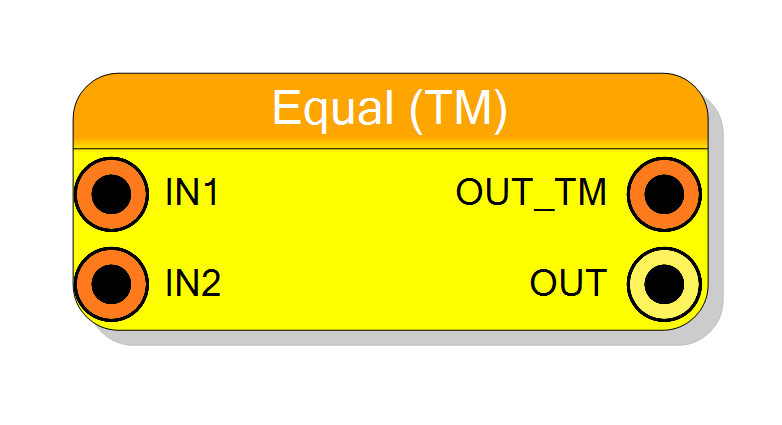
Time-multiplexed equality comparator that processes multiple comparison operations in parallel. Compares two TM data streams and outputs TM boolean results. Supports configurable TM factors (2-32) with optional mixed TM/STD input modes.
Introduction
This block performs parallel equality comparisons on time-multiplexed (TM) data streams. Each TM phase is compared independently, producing a TM boolean output:
$$ \mathrm{OUT_TM}[i] = \begin{cases} 1 & \text{if } \mathrm{IN1}[i] = \mathrm{IN2}[i] \ 0 & \text{otherwise} \end{cases} $$
for each TM phase $i = 0$ to $N-1$ where $N$ is the TM Factor.
The component supports two input modes:
- IN2 Mode = TM: Both inputs are time-multiplexed (phase-by-phase comparison)
- IN2 Mode = STD: IN2 is a single value compared against all IN1 phases
Pin Description
Properties
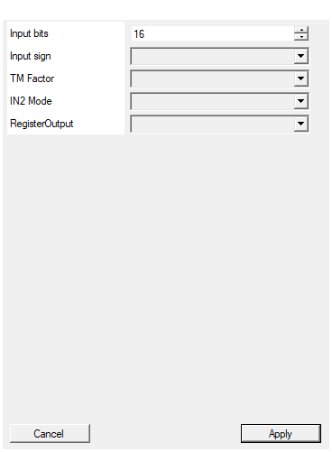
Set the number of bits of the input (per TM phase)
Number of bits per input sample (per TM phase). Range: 2-2048 bits. Applies to each slice of the TM data.Default: 16
Range: 2 – 2048
Select the sign/unsign of the input
Selects input interpretation: UNSIGNED (default) or SIGNED (two’s complement). For equality, this does not affect the result.Default: UNSIGNED
Options: UNSIGNED SIGNED
Select the TM Factor of the input
Time-multiplexing factor (number of parallel phases). Allowed values: 2, 4, 8, 16, 32. Higher values increase throughput but consume more resources.Default: 4
Options: 2 4 8 16 32
Select if IN2 is Time-Multiplexed or a single STD signal
Input mode for IN2: TM (time-multiplexed, phase-matched comparison) or STD (single value compared against all IN1 phases).Default: TM
Options: TM STD
Enable one pipeline stage adding a register
Adds output register stage. Disable (combinational, zero latency) or Enable (registered, 1 clock cycle latency).Default: Disable
Options: Disable Enable
Functional description
The Equal [TM] comparator replicates the standard Equal comparator N times in parallel, where N is the TM Factor. This enables efficient comparison of multiple data pairs per clock cycle.
TM-to-TM Comparison (IN2 Mode = TM)
When both inputs are TM: $$ \mathrm{OUT_TM}[i] = (\mathrm{IN1}[i] == \mathrm{IN2}[i]) \quad \text{for } i = 0 \ldots N-1 $$
Each phase is compared independently.
TM-to-STD Comparison (IN2 Mode = STD)
When IN2 is a standard (non-TM) signal: $$ \mathrm{OUT_TM}[i] = (\mathrm{IN1}[i] == \mathrm{IN2}) \quad \text{for } i = 0 \ldots N-1 $$
The single IN2 value is compared against all phases of IN1.
Time Multiplexing
Time multiplexing (TM) packs multiple data samples into a wider bus:
IN1 structure (TM Factor = 4, Input bits = 16):
IN1[63:0] = [Phase3][Phase2][Phase1][Phase0]
[15:0] [31:16] [47:32] [63:48]
Each 16-bit slice represents one sample in the TM stream.
Output Formats
The component provides two output pins:
- OUT_TM: TM boolean output (N bits, one per phase)
- OUT: Collapsed single-bit output (OR reduction of OUT_TM)
Latency and Timing
| RegisterOutput | Latency (clock cycles) |
|---|---|
| Disable | 0 |
| Enable | 1 |
All TM phases are processed in parallel within the same clock cycle.
Typical use cases
- High-throughput comparison in parallel data processing
- Multi-channel signal comparison
- Parallel pattern matching
- Vector equality checking