
Counter (Falling Edge)
Synchronous edge counter that counts falling edges on an input signal. Features gated counting control and overflow detection. Operates synchronously to system clock for glitch-free operation. Configurable counter width from 8 to 64 bits.
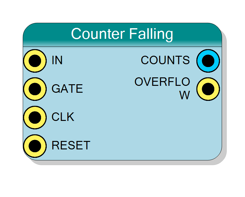
Introduction
This block counts falling edges (1→0 transitions) on the IN input signal. Functionally identical to the Rising Edge Counter but detects opposite polarity edges.
Key features:
- Counts falling edges on IN signal
- Synchronous operation (glitch-immune)
- Optional gating control via GATE input
- Overflow detection
- Configurable counter width (8-64 bits)
Operation:
- Detects falling edges on IN input (synchronized to CLK)
- Increments COUNTS by 1 for each falling edge detected
- GATE input enables/disables counting
- OVERFLOW pulses when counter wraps around
$$ \mathrm{COUNTS}(n+1) = \begin{cases} \mathrm{COUNTS}(n) + 1 & \text{if Falling Edge on IN and GATE=‘1’} \ \mathrm{COUNTS}(n) & \text{otherwise} \end{cases} $$
Pin Description
Input signal to count.
Falling edges (1→0 transitions) on this signal are counted.
Synchronization: Signal is sampled on CLK rising edge. Glitches shorter than one clock period are ignored.
Frequency limit: Maximum countable frequency is CLK_Frequency / 2. For reliable operation, keep IN frequency below CLK_Frequency / 4.
Edge detection: Falling edge detected when IN was ‘1’ in previous cycle and is ‘0’ in current cycle.
Gate control input (active high).
- ‘1’ = Counting enabled (falling edges counted)
- ‘0’ = Counting disabled (falling edges ignored, count holds value)
Useful for time-windowed or conditional counting.
Default: Connects to ‘1’ if left unconnected (always enabled).
Clock input.
Samples IN signal, clocks edge detection, updates counter.
Counter increments when falling edge detected and GATE=‘1’.
Default: Connects to global clock if left unconnected.
Synchronous reset input (active high).
- ‘1’ = Reset counter to 0, clear overflow flag
- ‘0’ = Normal operation
Default: Connects to global reset if left unconnected.
Current count output (unsigned integer).
Contains the number of falling edges detected since last reset.
Width: Configured by Bit Number property
Behavior:
- Increments by 1 for each falling edge on IN (when GATE=‘1’)
- Wraps to 0 after reaching maximum (2^BitNumber - 1)
- Holds value when GATE=‘0’
- Resets to 0 on RESET=‘0’
Registered output, stable and glitch-free.
Overflow flag output (single-cycle pulse).
Pulses high for one clock cycle when counter wraps from maximum value to 0.
Can be used for overflow detection or extended precision counting.
Registered output, synchronous to CLK.
Properties
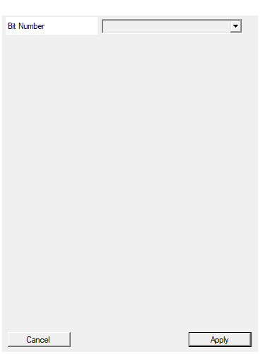
Set the number of bit used in the counter accumulator
Number of bits in the counter.
Available values: 8, 16, 24, 32, 40, 48, 56, 64
Determines maximum count and COUNTS output width.
Choose based on maximum expected edge count between resets.
Default: 32
Options: 8 16 24 32 40 48 56 64
Functional description
The counter implements synchronous falling edge detection by registering the IN signal and comparing consecutive values:
Edge detection mechanism
$$ \text{Falling Edge} = \overline{\text{IN}(n)} \land \text{IN}(n-1) $$
Where:
- IN(n) = Current value of IN signal
- IN(n-1) = Previous value of IN signal (from last clock)
- ∧ = AND operation
- ‾ = NOT operation
A falling edge is detected when:
- Previous cycle: IN=‘1’
- Current cycle: IN=‘0’
Synchronous operation
All edge detection is synchronized to the system clock (CLK):
- IN signal sampled on each CLK rising edge
- Provides immunity to glitches shorter than one clock period
- Introduces 1-2 cycle latency for edge detection
- Maximum countable frequency: CLK_Frequency / 2 (Nyquist limit)
Operation comparison
| Counter Type | Detects | Example: Count Pulses |
|---|---|---|
| Rising Edge | 0→1 transition | Count pulse starts |
| Falling Edge | 1→0 transition | Count pulse ends |
| Both Edges | Both 0→1 & 1→0 | Count both starts & ends |
Timing diagram
The diagram shows:
- IN signal synchronized to CLK
- Falling edges detected (1→0 transitions)
- Counter increments on each falling edge
- One clock cycle latency from edge to count
Typical use cases
- Pulse completion counting: Count when pulses end (complementary to rising edge)
- Negative-going event counting: Count events marked by falling edges
- Clock division verification: Count falling edges of divided clock
- Duty cycle measurement: Combined with rising edge counter to measure duty cycle
- Return-to-zero detection: Count completions of active-high events
- Sensor falling edge: Some sensors signal events on falling edges
Design considerations
Input signal requirements
Same as Rising Edge Counter:
- Maximum input frequency: CLK_Frequency / 2
- Minimum high/low time: 1 clock period each
- Minimum period: 2 clock periods
- Glitch immunity: < 1 clock period
Choosing between Rising and Falling Edge counters
Use Rising Edge Counter when:
- Events are marked by 0→1 transitions
- Counting pulse starts
- Following standard digital logic conventions
Use Falling Edge Counter when:
- Events are marked by 1→0 transitions
- Counting pulse ends
- Sensor outputs active-low pulses
- Need complementary counting to rising edges
Use Both Edges Counter when:
- Need to count complete cycles (rising + falling)
- Frequency doubling effect needed
- Both transitions are significant events
Combined duty cycle measurement
Use both Rising and Falling counters together:
$$ \text{Duty Cycle} = \frac{\text{Rising Count}}{\text{Rising Count} + \text{Falling Count}} $$
Example: For a 60% duty cycle signal with 100 complete cycles:
- Rising edge counter: 100
- Falling edge counter: 100
- High time = 60 cycles × CLK_period
- Low time = 40 cycles × CLK_period