
Petiroc Frame Transfer
Event builder and host readout endpoint for up to four PETIROC-2A chips. It round-robins over the four digital readout channels, wraps each 1024-bit payload in a 38-word frame with a header, two timestamps, a packet counter and a trailer, pushes it into a configurable FIFO, and exposes it to the host through the generated SciSDK download and decode functions.
Introduction
Principle of Operation
A DT5550W carries four PETIROC-2A chips, each read out by its own Petiroc Digital block. Those four blocks produce events asynchronously. This block merges them into one ordered stream and gives the host a single FIFO to read.
Petiroc Digital A ──► DATA_A / TS_T0_A / TS_A / DV_A ──┐
Petiroc Digital B ──► … │ ┌──────────┐
Petiroc Digital C ──► … ├──►│ arbiter │
Petiroc Digital D ──► … │ │ A→B→C→D │
┘ └────┬─────┘
│ 38 words
┌─────▼──────┐
│ async FIFO │──► host
│ memLength │
└────────────┘
The arbiter visits one input per clock cycle (A, B, C, D, A, …). When the
visited input has DV high and is not disabled in the control register, the
whole frame is assembled in a 38 × 32-bit latch in a single clock, the input
is acknowledged, and the frame is then streamed into the FIFO one word per
clock for the next 38 clocks.
The frame
Every event is exactly 38 words of 32 bits:
| Word | Content | Written by the HDL as |
|---|---|---|
| 0 | header, 0x8000000N where N = 0/1/2/3 = ASIC A/B/C/D |
x"8000000<n>" |
| 1 | TS_T0_x – 32-bit local time code (T0-referenced) |
TS_T0_x |
| 2 | TS_x[31:0] – low half of the 64-bit global timestamp |
TS_x(31 downto 0) |
| 3 | TS_x[63:32] – high half |
TS_x(63 downto 32) |
| 4 | packet id – free-running event counter, shared by all four ASICs | TotalEventCounter |
| 5 … 36 | the 32 payload words straight from DATA_x |
DATA_x |
| 37 | trailer, 0xC0000000 |
x"C0000000" |
The host resynchronises on the header (word >> 4 == 0x8000000) and validates
on the trailer (word & 0xC0000000 == 0xC0000000); a frame whose trailer does
not match is discarded and the decoder goes back to hunting for a header.
Pin Description
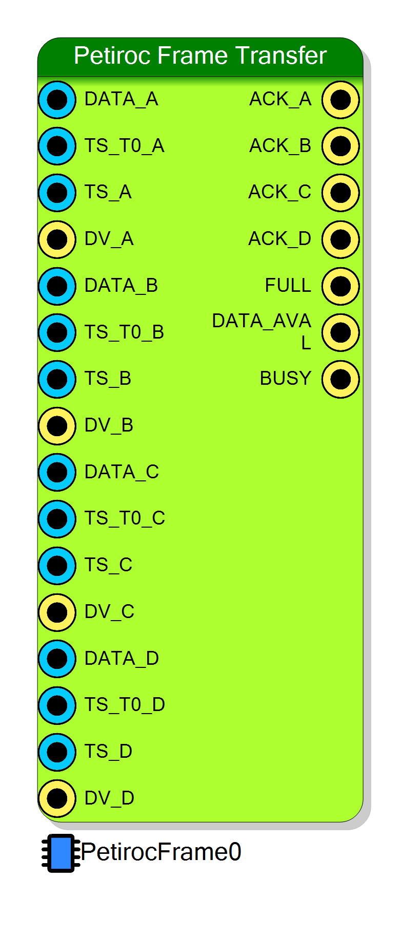
DATA_WORD output of the Petiroc
Digital block bound to ASIC A. Copied verbatim into words 5…36 of the
frame; this block never looks inside it.
TS_T0 output of the matching Petiroc Digital block.
TS_GLOABAL output of the matching Petiroc
Digital block.
CONTROL(0) is 0) the frame is latched and
ACK_A is pulsed. Leaving it open, or masking it with CONTROL(0),
removes ASIC A from the rotation.
DATA_A.
TS_T0_A.
TS_A.
DV_A; masked by CONTROL(1).
DATA_A.
TS_T0_A.
TS_A.
DV_A; masked by CONTROL(2).
DATA_A.
TS_T0_A.
TS_A.
DV_A; masked by CONTROL(3).
DV_ACK of the Petiroc Digital block on
ASIC A. Note that it is issued even when the FIFO had no room and the
frame was dropped - see the alert about silent drops.
ACK_A.
ACK_A.
ACK_A.
STATUS(0).
Properties
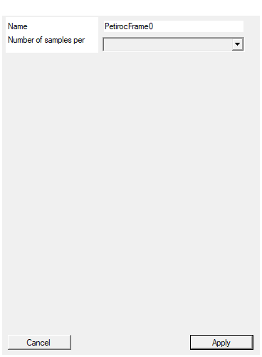
Set the name of the endpoint
Name of the memory-mapped FIFO endpoint. It prefixes every generated
symbol - SCI_REG_<EndpointName>_FIFOADDRESS,
SCI_REG_<EndpointName>_CONTROL, SCI_REG_<EndpointName>_STATUS,
PETIROCFRAME_<EndpointName>_START/_RESET/_GetStatus/_DOWNLOAD/_RECONSTRUCT_DATA
- and names the wrapper signals
REG_<EndpointName>_CONTROL_WR,BUS_<EndpointName>_READ_DATA. Must be unique in the project and a valid C/Python identifier. Changing it rebuilds the symbol.
Default: PetirocFrame0
Default: PetirocFrame0
Set the number of samples stored for each acquisition
Depth of the readout FIFO, bound to the VHDL generic memLength. Despite
the caption (“Number of samples per channel”) the unit is 32-bit FIFO
words, not samples: the buffer holds floor(memLength / 38) complete
events.
| Setting | Events buffered | Usable? |
|---|---|---|
| 1024 | 26 | yes |
| 4096 | 107 | yes |
| 8192 | 215 | yes |
| 16384 | 431 | yes |
| 32768 | 862 | yes |
| 65536 | 1724 | yes (status field ends exactly at bit 31) |
| 131072 | 3449 | no – status slice overflows, see the alert |
| 262144 | 6898 | no – status slice overflows, see the alert |
Size it from the burstiness of the source rather than the average rate: the FIFO absorbs bursts, and once it is full, events are dropped silently.
Default: 8192
Default: 8192
Options: 1024 4096 8192 16384 32768 65536 131072 262144
⚙️ Detailed Operation
Payload layout - the authoritative field map
Words 5…36 are the raw bit stream the ASIC sent, packed by Petiroc Digital
as "00" & <30 ASIC bits> per word. The host decoder re-cuts each of those 32
words into three 10-bit fields:
datarow[j*3 + 0] = (word >> 20) & 0x3FF; /* first 10 bits received */
datarow[j*3 + 1] = (word >> 10) & 0x3FF;
datarow[j*3 + 2] = (word >> 0) & 0x3FF; /* last 10 bits received */
for j = 0 … 31, giving 96 fields (32 words × 30 bits ÷ 10). Those 96
fields map onto the 32 channels as:
| Field index | Meaning | Encoding |
|---|---|---|
datarow[2i + 0], i = 0…31 |
fine time of channel i (TDC interpolator) | 10-bit Gray |
datarow[2i + 1], i = 0…31 |
charge of channel i | 10-bit Gray |
datarow[64 + i], i = 0…31 |
hit flag of channel i, bit 0 only | plain bit |
i.e. the first 64 fields are per-channel (fine time, charge) pairs
interleaved, and the last 32 fields carry one hit bit each. All 10-bit
values are Gray coded - the decoder calls gray_to_bin(value, 10) on every
one of them. If you decode the frame yourself, the Gray conversion is not
optional.
word 5 word 6 … word 36
┌──────────┐ ┌──────────┐ ┌──────────┐
│00│f0│q0│f1│ │00│q1│f2│q2│ … │00│h29│h30│h31│
└──────────┘ └──────────┘ └──────────┘
f = fine time (gray10) q = charge (gray10) h = hit (bit 0 of a 10-bit field)
Arbitration and event loss
The arbiter advances ARBITERID every clock, so the four inputs are polled in
a fixed A → B → C → D rotation. Writing a frame occupies the FIFO port for 38
clocks, during which no other input is polled - the worst-case service latency
for an input that raises DV just after its slot is
3 + 38 = 41 clock cycles.
Control and status registers
CompileMMC declares a FIFO-read endpoint with two registers, CONTROL (W)
and STATUS (R), plus the FIFO address itself.
CONTROL (write only):
| Bit | Function |
|---|---|
| 0 | 1 = ignore DV_A (disable ASIC A) |
| 1 | 1 = ignore DV_B |
| 2 | 1 = ignore DV_C |
| 3 | 1 = ignore DV_D |
| 8 | 1 = hold the block in reset: flush the FIFO, clear the packet counter, clear the arbiter |
Bit 8 is level sensitive and sits outside the clocked branch, so writing
0x100 holds the block in reset until something else is written. That is
exactly what the generated start-up pair does:
PETIROCFRAME_<name>_RESET(&handle); /* writes 0x100 -> flush + hold */
PETIROCFRAME_<name>_START(&handle); /* writes 0x000 -> release */
STATUS (read only):
| Bits | Function |
|---|---|
| 0 | data available - at least one complete frame is in the FIFO |
| 16 + | FIFO word count (rd_data_count) |
read back by PETIROCFRAME_<name>_GetStatus(&is_data_available, &word_available, &handle) as temp & 0x01 and (temp >> 16) & 0xFFFF.
The FIFO
An xpm_fifo_async of memLength 32-bit words (the Samples property),
read latency 1, standard (non-FWFT) read mode, 2 CDC stages. Both its write
and read clocks are wired to the project’s global clock by CompileHDL, so in
a stock design it behaves as a synchronous FIFO; the asynchronous primitive is
there so the host-side read port can be moved to another clock.
Thresholds are chosen in units of one frame:
PROG_FULL_THRESH = memLength - 38→FULLasserts when there is less than one frame of room left, which is what makes the dropped-frame case above the only failure mode instead of a torn frame.PROG_EMPTY_THRESH = 38→DATA_AVALandSTATUS(0)assert only when at least one complete frame is present, so a host that reads 38 words when the flag is set always gets a whole event.
Event capacity is floor(memLength / 38): 215 events at the default 8192
words.
Host read sequence
c
void *buf = NULL;
Utility_ALLOCATE_DOWNLOAD_BUFFER(&buf, 1024*1024);
PETIROCFRAME_PetirocFrame0_RESET(&handle);
PETIROCFRAME_PetirocFrame0_START(&handle);
while (1) {
uint32_t avail = 0, words = 0;
PETIROCFRAME_PetirocFrame0_GetStatus(&avail, &words, &handle);
if (!avail) continue;
PETIROCFRAME_PetirocFrame0_DOWNLOAD(data_frame, N_Packet * 38,
timeout_ms, &handle,
&read_data, &valid_data);
Utility_ENQUEUE_DATA_IN_DOWNLOAD_BUFFER(buf, data_frame, valid_data, &enqueued);
PETIROCFRAME_PetirocFrame0_RECONSTRUCT_DATA(buf, &decoded_packets);
for (int i = 0; i < decoded_packets.valid_packets; i++)
/* .Pack_Id .Time_Code .RunTime_Code .AsicID
.Charge[32] .Hit[32] .FineTime[32] */ ;
free_PETIROCFRAME_packet_collection(&decoded_packets);
}
The decoder is stream oriented: it is fed from a circular buffer, so a
download that cuts a frame in half is recovered on the next call. It returns
-1 if the buffer holds less than one frame and -2 if it cannot allocate
the output arrays.
The Python library generated alongside offers
PETIROCFRAME_<name>_RESET/_START/_GET_STATUS/_GET_DATA/_RECONSTRUCT_DATA,
the last returning
AsicId, Time_Code, RunTime_Code, Pack_Id, Charge, Hit, Fine, Coarse.
Wiring note
Unused ASIC inputs may be left open; their DV_x then reads as the pad
default and the corresponding control bit can be set to 1 to make the mask
explicit. ACK_x must go back to the DV_ACK pin of the matching Petiroc
Digital block, otherwise DV is never cleared and the same event is
re-latched on every rotation.
Resources & Timing
-
Latency: Up to 3 clocks of arbitration plus 38 clocks to stream one frame into the FIFO; worst case 41 clocks from DV to the last word written.
-
Throughput: One frame per 38 clocks, i.e. up to ≈ 4.2 Mevents/s at 160 MHz, far above what a PETIROC-2A readout can produce. The real limit is the host link.
- Frame size is fixed at 38 words of 32 bits (152 bytes) regardless of how many channels actually fired.
- The packet counter in word 4 is shared by all four ASICs, so it orders events across chips and its gaps reveal drops.
- The entity has a
resetport, but the architecture never reads it: the block is reset only by the framework’s FIFO reset net or byCONTROLbit 8.