
ALU - NOISE FILTER (MOVING AVERAGE)
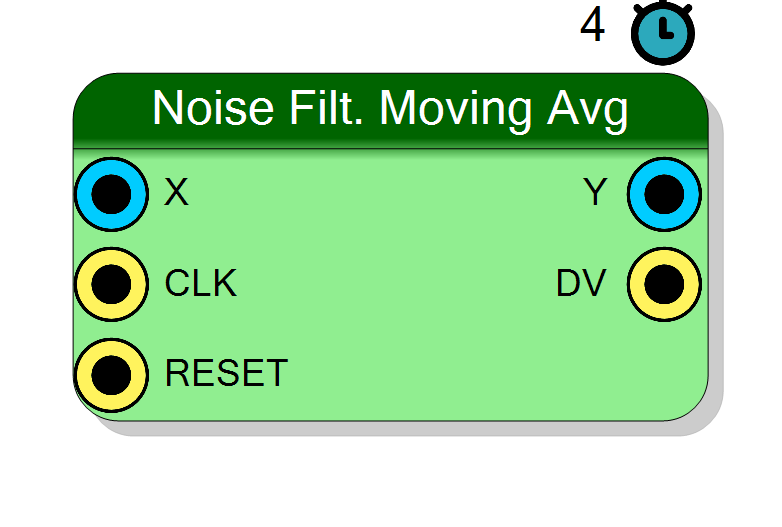
Simple moving average noise filter implemented via Vivado HLS. Averages 4, 8, 16, or 32 consecutive samples to reduce noise. Uses distributed RAM (LUTRAM) for minimal resource usage.
Introduction
The Noise Filter block implements a simple moving average filter:
$$ y[n] = \frac{1}{N} \sum_{k=0}^{N-1} x[n-k] $$
where:
Nis the number of samples (4, 8, 16, or 32)x[n-k]are the delayed input samples
This is an efficient noise reduction technique that:
- Averages out random noise
- Preserves DC and low-frequency content
- Has simple, predictable frequency response
- Uses minimal FPGA resources (distributed RAM)
Pin Description
Properties
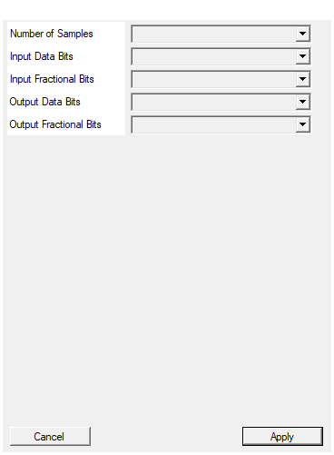
Number of samples for moving average (4, 8, 16, or 32)
Number of samples to average. Options: 4, 8, 16, or 32. Higher values provide more noise reduction but slower response.
Trade-offs:
- 4 samples: Fastest response, -6 dB noise reduction
- 8 samples: Good balance, -9 dB noise reduction
- 16 samples: Strong filtering, -12 dB noise reduction
- 32 samples: Maximum filtering, -15 dB noise reduction
Default: 8
Options: 4 8 16 32
Total bit width of input data (8-32 bits)
Total bit width of input data X. Range: 8-32 bits. Includes both integer and fractional parts.Default: 16
Options: 8 9 10 11 12 13 14 15 16 17 18 19 20 21 22 23 24 25 26 27 28 29 30 31 32
Number of fractional bits in input data (0-16)
Number of fractional bits in input data. Range: 0-16 bits. Integer bits = InDataBits - InFractBits.Default: 0
Options: 0 1 2 3 4 5 6 7 8 9 10 11 12 13 14 15 16
Total bit width of output data (8-64 bits)
Total bit width of output data Y. Range: 8-64 bits. Should be at least InDataBits for no precision loss.Default: 16
Options: 8 9 10 11 12 13 14 15 16 17 18 19 20 21 22 23 24 25 26 27 28 29 30 31 32 33 34 35 36 37 38 39 40 41 42 43 44 45 46 47 48 49 50 51 52 53 54 55 56 57 58 59 60 61 62 63 64
Number of fractional bits in output data (0-32)
Number of fractional bits in output data. Range: 0-32 bits. For best precision, match InFractBits.Default: 0
Options: 0 1 2 3 4 5 6 7 8 9 10 11 12 13 14 15 16 17 18 19 20 21 22 23 24 25 26 27 28 29 30 31 32
Functional description
The moving average filter computes the arithmetic mean of the last N samples:
$$ y[n] = \frac{x[n] + x[n-1] + x[n-2] + \ldots + x[n-N+1]}{N} $$
Division by power of 2
Since N is always a power of 2 (4, 8, 16, or 32), division is implemented as a simple right bit shift, requiring no actual divider hardware:
| N | Division | Shift |
|---|---|---|
| 4 | /4 | » 2 |
| 8 | /8 | » 3 |
| 16 | /16 | » 4 |
| 32 | /32 | » 5 |
Transfer function
In the z-domain, the moving average filter has the transfer function:
$$ H(z) = \frac{1}{N} \sum_{k=0}^{N-1} z^{-k} = \frac{1}{N} \cdot \frac{1 - z^{-N}}{1 - z^{-1}} $$
Frequency response
The moving average has a sinc-like frequency response with:
- Unity gain at DC (0 Hz)
- Nulls at frequencies f = k * fs/N (where k = 1, 2, 3, …)
- First null at fs/N
| N | First null frequency |
|---|---|
| 4 | fs/4 = 0.25 * Nyquist |
| 8 | fs/8 = 0.125 * Nyquist |
| 16 | fs/16 = 0.0625 * Nyquist |
| 32 | fs/32 = 0.03125 * Nyquist |
Noise reduction
For white noise, the moving average reduces RMS noise by:
$$ \text{Noise reduction} = \sqrt{N} $$
| N | Noise reduction | dB |
|---|---|---|
| 4 | 2x | -6 dB |
| 8 | 2.83x | -9 dB |
| 16 | 4x | -12 dB |
| 32 | 5.66x | -15 dB |
Resource usage
The filter uses distributed RAM (LUTRAM) instead of Block RAM:
- N delay registers implemented in LUTs
- N-input adder tree
- No multipliers required
- Minimal routing resources
Latency
Fixed latency of 4 clock cycles (HLS pipeline). The DV output goes high after N samples have been processed.
Typical use cases
- ADC noise reduction
- Sensor signal smoothing
- DC level extraction
- Simple low-pass filtering
- Baseline stabilization