
Multiplexer
N-to-1 multiplexer that routes one of multiple inputs to a single output based on a binary select signal. Supports 2 to 16384 inputs with configurable word size. Pure combinational logic with zero latency.
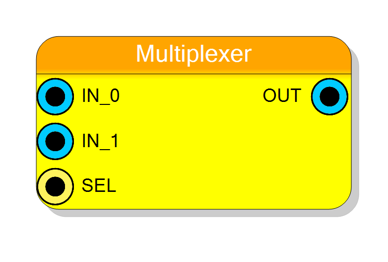
Introduction
This block implements a standard multiplexer (MUX) that selects one input from multiple sources and routes it to the output. The selection is controlled by a binary select signal:
$$ \mathrm{OUT} = \mathrm{IN}_{\mathrm{SEL}} $$
Where SEL is interpreted as a binary number indicating which input to route.
Pin Description
Properties
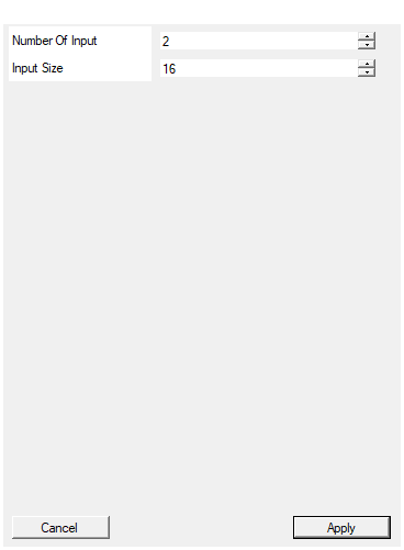
Set the number of inputs
Number of input ports. Range: 2-16384. Determines how many IN_x ports are created and the width of the SEL signal.Default: 2
Range: 2 – 16384
Set the size in bit of inputs
Number of bits for each input and the output. Range: 1-16384 bits. All data ports must have the same width.Default: 16
Range: 1 – 16384
Functional description
The Multiplexer component implements an N-to-1 data selector. It has N input ports (IN_0 to IN_(N-1)) and uses a select signal to determine which input is routed to the output.
Selection Operation
$$ \mathrm{OUT} = \mathrm{IN_i} \quad \text{where } i = \mathrm{SEL} $$
The select signal width is automatically calculated as: $$ \text{SEL width} = \lceil \log_2(N) \rceil \text{ bits} $$
Example
For a 4-to-1 MUX (4 inputs):
- SEL width = 2 bits
- SEL = 00 (0) → OUT = IN_0
- SEL = 01 (1) → OUT = IN_1
- SEL = 10 (2) → OUT = IN_2
- SEL = 11 (3) → OUT = IN_3
Unconnected Inputs
If an input is not connected, it is automatically replaced with a zero vector. A warning is generated during compilation for each unconnected input.
Out of Range Selection
If SEL exceeds the number of inputs, the output is driven to all zeros.
Implementation
The multiplexer is implemented as a pure combinational selector using VHDL conditional assignment. This results in efficient hardware (typically implemented as LUT-based logic in FPGAs).
Latency and Timing
| Property | Latency (clock cycles) |
|---|---|
| Multiplexer | 0 |
The component has zero latency (purely combinational).
Typical use cases
- Data path switching and routing
- Source selection in data processing pipelines
- Time-division multiplexing
- Building larger multiplexer trees
- Configuration and mode selection