
FLOATING POINT - MULTIPLICATION
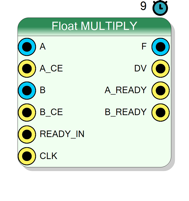
Performs IEEE-754 floating-point multiplication with configurable DSP usage. Supports both single-precision (32-bit) and double-precision (64-bit) formats. Built on Xilinx Floating-Point IP core with blocking flow control and 9-cycle latency.
Introduction
The block performs floating-point multiplication of two IEEE-754 encoded values.
On every rising edge of CLK, if both A_CE = 1 and B_CE = 1, the multiplier computes
$$ \mathrm{F}(n) = \mathrm{A}(n) \times \mathrm{B}(n), $$
where inputs A, B and output F follow IEEE-754 single or double
precision format.
The multiplication is implemented with the Xilinx floating_point IP core configured for Multiply operation with blocking flow control, fixed 9-cycle latency, and configurable DSP primitive usage for optimized performance.
Pin Description
A_CE = 1 and A_READY = 1.
A_CE = 1, input A is accepted into the pipeline. Can be tied to ‘1’ for continuous operation.
B_CE = 1 and B_READY = 1.
B_CE = 1, input B is accepted into the pipeline. Can be tied to ‘1’ for continuous operation.
DV = 1.
Result = A × B.
F contains a valid product.
Asserts 9 clock cycles after corresponding inputs accepted.
A.
Used for flow control on A channel.
B.
Used for flow control on B channel.
Properties
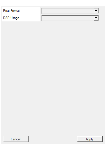
Select between single precision 32 bit and double precision 64 bit
Floating-point precision for all inputs and output:
- Single → 32-bit (8-bit exponent, 24-bit mantissa including implicit bit)
- Double → 64-bit (11-bit exponent, 53-bit mantissa including implicit bit)
All operands must use the same precision.
Default: Single
Options: Single Double
DSP Usage. Single precision: No [0], Medium [1], Full[2], Max[3]. Double precision: No[0], Medium [9], Full[10], Full[11]
DSP primitive allocation strategy:
- No_Usage → LUT-only (0 DSPs, lowest speed)
- Medium_Usage → Partial DSP (1/9 DSPs for Single/Double)
- Full_Usage → Standard DSP (2/10 DSPs, recommended, good speed)
- Max_Usage → Maximum DSP (3/11 DSPs, highest speed)
Higher usage trades DSP48 resources for improved maximum clock frequency.
Default: Full_Usage
Options: No_Usage Medium_Usage Full_Usage Max_Usage
Functional description
The component performs IEEE-754 compliant floating-point multiplication:
$$ F = A \times B $$
The operation handles:
- Exponent addition with bias correction
- Mantissa multiplication (24×24 or 53×53 bits)
- Result normalization
- Rounding (round-to-nearest, ties-to-even)
Special cases
IEEE-754 special value handling:
0 × x = 0(for finite x)+Inf × x = +Inf(for finite x > 0)0 × Inf = NaN(invalid operation)NaN × x = NaN(NaN propagation)
DSP Usage
The DSP Usage property controls resource allocation for the mantissa multiplication:
Single precision:
- No_Usage → Pure LUT implementation (0 DSPs, lower speed)
- Medium_Usage → Partial DSP optimization (1 DSP)
- Full_Usage → Standard DSP optimization (2 DSPs, recommended)
- Max_Usage → Maximum DSP optimization (3 DSPs, highest speed)
Double precision:
- No_Usage → Pure LUT implementation (0 DSPs, lower speed)
- Medium_Usage → Partial DSP optimization (9 DSPs)
- Full_Usage → Standard DSP optimization (10 DSPs, recommended)
- Max_Usage → Maximum DSP optimization (11 DSPs, highest speed)
Higher DSP usage improves timing but consumes more DSP48 primitives.
Timing
The IP has a fixed 9-cycle pipeline latency:
| Clock cycle | Event |
|---|---|
| 0 | Inputs A, B presented with A_CE = 1, B_CE = 1 |
| 9 | Output F valid with DV = 1 |
The separate A_READY/B_READY handshake signals enable independent
backpressure control for each input.
Typical use cases
- Scaling operations in signal processing
- Complex number multiplication (4 real multiplications)
- Matrix operations (dot products, matrix-vector multiply)
- Power and energy calculations