
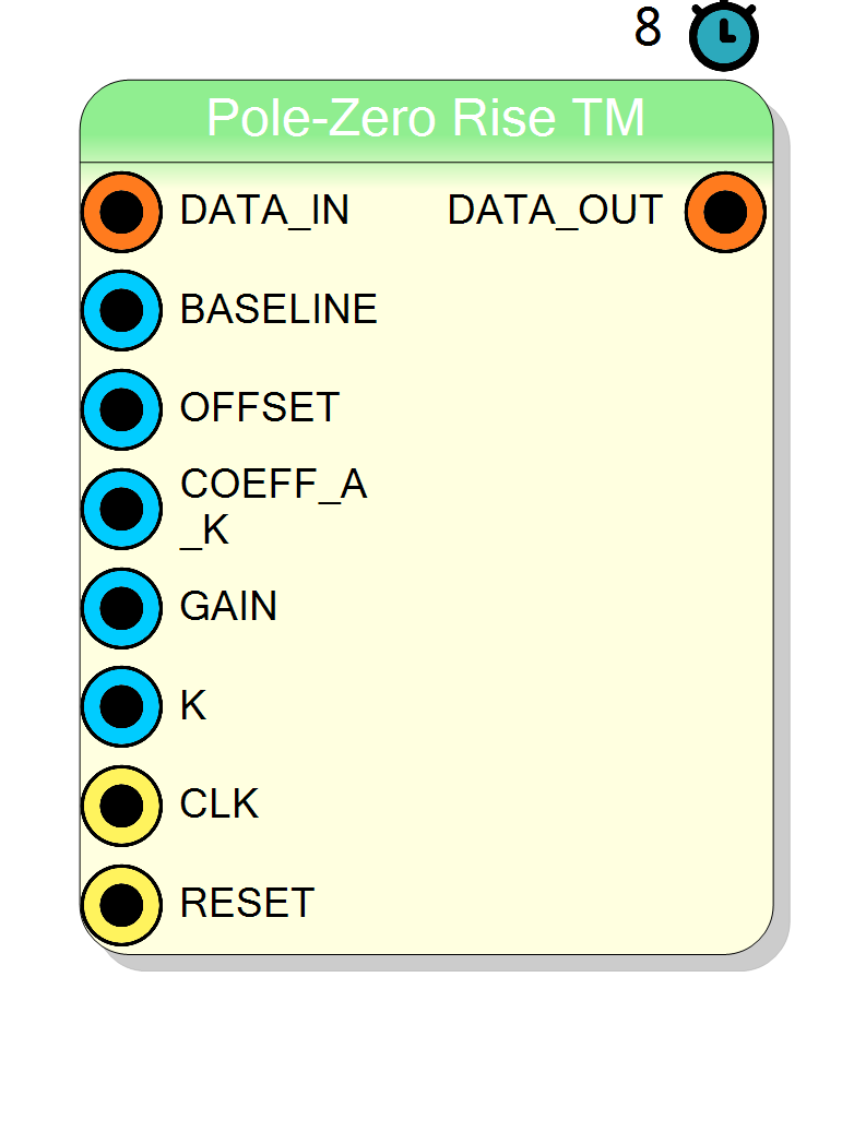
Pole-Zero Rise TM
Time-multiplexed digital Pole-Zero Compensation with programmable rise-time delay K. Designed for preamplifiers with slow rise time, where the standard PZ (K=1) fails to capture the full signal amplitude. The delay K spans the entire rise edge, dramatically improving SNR on slow-rise signals.
Introduction
The Pole-Zero Rise TM block implements a variant of digital pole-zero cancellation optimized for slow-rise preamplifier signals.
The standard PZ block computes y[n] = gain × (x[n] − a × x[n−1]). With fast-rise signals (step-like), this works perfectly. However, with slow-rise preamplifiers (e.g. charge-sensitive preamps with finite bandwidth), the difference x[n] − a·x[n−1] is near zero during the rise phase because consecutive samples are almost identical. Most of the signal energy is lost, and the SNR degrades severely.
This block solves the problem by delaying the subtraction by K samples instead of 1:
$$ y[n] = \text{gain} \cdot (x[n] - a_K \cdot x[n-K]) $$
By choosing K to match the 10%–90% rise time of the preamplifier, the difference spans the full rise edge and captures the complete signal amplitude. The noise remains comparable because the operation is still a single subtraction and multiply — the same complexity as the standard PZ.
When K=1, this block behaves identically to the standard Pole-Zero TM block.
The core uses Xilinx HLS (High-Level Synthesis) for efficient FPGA implementation, achieving a throughput of 1 word per clock cycle (II=1) while processing multiple TM samples in parallel.
Pin Description
a_K in 32-bit fixed-point format.
Format: 2 integer bits, 30 fractional bits (Q2.30).
Calculated as: COEFF_A_K = int(exp(-K * Ts / tau) * 2^30)
where Ts is sampling period, tau is preamplifier decay time, and K is the rise-time delay.
Note: this coefficient depends on K. When K changes, a_K must be recalculated.
GAIN = int((1/(1 - a_K)) * 2^16)
Note: this coefficient depends on K. When K changes, gain must be recalculated.
Properties
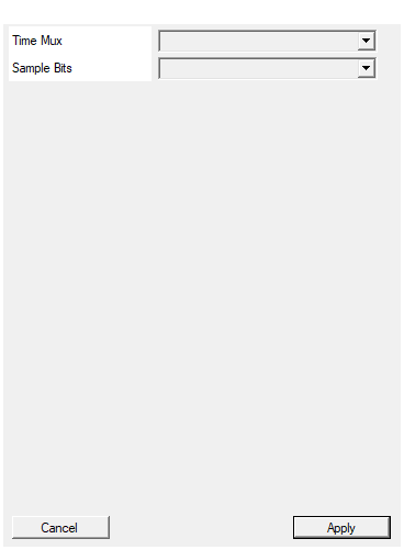
Set number of samples for each clock cycle
Number of parallel samples processed per clock cycle (TM factor). Available values: 2, 4, 8, 16, 32, default 4.Default: 4
Options: 2 4 8 16 32
Set number of bits for each sample
Bit-width of each sample within the TM frame. Applies toDATA_IN, BASELINE, OFFSET and DATA_OUT signals.
Available values: 8, 10, 12, 14, 16, 18, 20, 22, 24, default 16.
Default: 16
Options: 8 10 12 14 16 18 20 22 24
Usage
Why Standard PZ Fails on Slow-Rise Signals
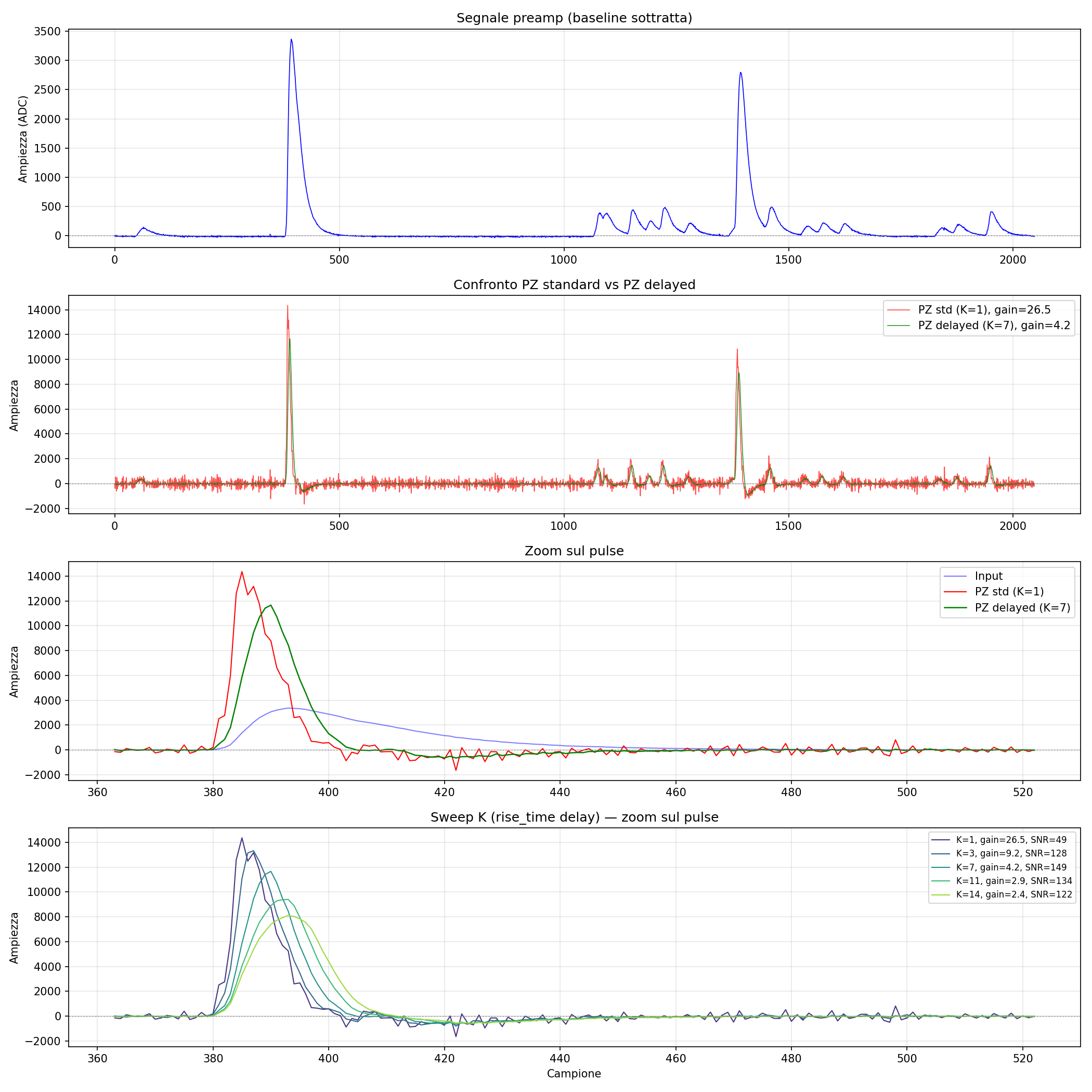
The figure compares the standard PZ (K=1, red) with the delayed PZ (K=7, green) on a real preamplifier signal with ~7 sample rise time.
- Standard PZ (K=1): the output oscillates wildly because each single-sample difference during the slow rise produces a separate spike. The noise floor is ~190 counts.
- Delayed PZ (K=7): a single clean pulse is produced. The noise floor drops to ~78 counts. SNR improves by 2×.
The improvement comes from matching the delay to the rise time: the subtraction x[n] − a_K·x[n−K] sees the full amplitude difference across the entire rise edge in one shot, instead of many tiny increments.
Transfer Function
$$ H(z) = \text{gain} \cdot (1 - a_K \cdot z^{-K}) $$
In the time domain, for each sample:
$$ y[n] = \text{gain} \cdot (x[n] - a_K \cdot x[n-K]) $$
where:
x[n]is the baseline-subtracted input sampley[n]is the output sampleKis the rise-time delay in samples (programmable, 1 to 64)a_Kis the pole-zero coefficient for delay Kgaincompensates for the amplitude reduction
Calculating COEFF_A_K from Decay Time Constant and K
The coefficient a_K must account for K samples of exponential decay:
$$ a_K = e^{-K \cdot T_s / \tau} = a_1^K $$
where:
- $T_s$ is the sampling period (1 / sampling_frequency)
- $\tau$ is the preamplifier decay time constant
- $a_1 = e^{-T_s/\tau}$ is the standard single-sample PZ coefficient
Fixed-point representation:
The coefficient is represented as a 32-bit fixed-point number with 2 integer bits and 30 fractional bits:
$$ \text{COEFF_A_K} = \left\lfloor a_K \cdot 2^{30} \right\rfloor $$
Example calculation (Python):
python
import math
sampling_freq = 125e6 # 125 MHz
tau = 50e-6 # 50 µs preamplifier decay time
K = 7 # rise-time delay in samples
Ts = 1.0 / sampling_freq # 8 ns
a_K = math.exp(-K * Ts / tau) # ≈ 0.99889
COEFF_A_K = int(a_K * (2**30))
# Result: COEFF_A_K = 1073622014
Calculating GAIN
The gain compensates for the amplitude reduction:
$$ \text{gain} = \frac{1}{1 - a_K} $$
Note: gain decreases as K increases (because a_K decreases), which is one reason the delayed PZ has lower noise — less amplification.
Fixed-point representation:
The gain is represented as a 32-bit fixed-point number with 16 integer bits and 16 fractional bits:
$$ \text{GAIN} = \left\lfloor \text{gain} \cdot 2^{16} \right\rfloor $$
Example calculation (Python):
python
gain = 1.0 / (1.0 - a_K)
GAIN = int(gain * (2**16))
Choosing K
K should match the 10%–90% rise time of the preamplifier signal, measured in samples:
$$ K = \left\lfloor \frac{t_{10-90}}{T_s} \right\rfloor $$
Guidelines:
- K=1: equivalent to the standard Pole-Zero TM block. Use for fast-rise signals (e.g. silicon detectors with fast preamps).
- K=3–10: typical for charge-sensitive preamplifiers with moderate bandwidth.
- K>10: for very slow preamps (e.g. high-capacitance detectors). Consider if K exceeds 64 whether the preamp bandwidth is adequate.
K is runtime-programmable, so it can be tuned from software without recompiling the firmware.
Baseline Subtraction
The block subtracts a programmable BASELINE value from each input sample before processing. This allows:
- Removal of DC offset from the ADC
- Compensation for baseline drift
- Centering the signal around zero for proper deconvolution
Output Offset
After deconvolution, the OFFSET value is added to shift the output signal to the desired range. This is useful when:
- The downstream processing expects unsigned values
- A specific DC level is required for triggering
Time-Multiplexed Processing
The block processes TM samples per clock cycle in parallel. Internally, the delay line correctly handles cross-subchannel indexing: a delay of K samples may span across subchannels within and across words. This is transparent to the user.
Fixed-Point Precision
Internal calculations use extended precision to prevent overflow:
- coeff_t: 32 bits, 2 integer bits, 30 fractional bits (for coefficient a_K)
- gain_t: 32 bits, 16 integer bits, 16 fractional bits (for gain)
- signal_t: 32 bits, 17 integer bits, 15 fractional bits (for signals)
- accum_t: 48 bits, 33 integer bits, 15 fractional bits (for accumulator)
FPGA Resources
The delay line is implemented as distributed LUTRAM (no BRAM consumed). The buffer is duplicated internally to achieve II=1 with cross-subchannel reads.
Typical resources (xc7z020, TM=4, 16-bit samples):
- BRAM: 0
- DSP: 0
- FF: ~3500
- LUT: ~1200
Latency
- Processing latency: ~23 clock cycles from input to output
- Throughput: TM samples per clock cycle (fully pipelined, II=1)
Typical Applications
- Signal conditioning for slow-rise charge-sensitive preamplifiers
- Pile-up reduction in high count-rate spectroscopy with bandwidth-limited preamps
- Pre-processing for trapezoidal shapers
- Baseline restoration in MCA systems
- Any application where the standard PZ produces oscillations or low SNR due to finite rise time