
RF Hilbert (real -> I/Q)
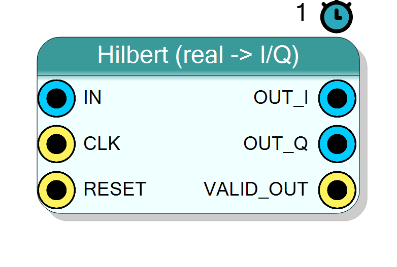
Hilbert-transformer FIR that turns a REAL input stream into an analytic I/Q pair at the SAME centre frequency (no down-conversion). Q is the 90-degree phase-shifted input, I is the input delayed by the group delay, so I + jQ is the analytic (single-sideband) signal. Typical use: feed a real passband signal into the complex-baseband RF chain (AM/FM demod, mixer, power meter) without a separate quadrature LO.
Introduction
The Hilbert (real -> I/Q) block is a Type III linear-phase FIR that synthesises the analytic signal from a single real input. The Q output is the Hilbert transform of the input (a broadband 90-degree phase shift); the I output is the input delayed by the filter group delay so I and Q are time-aligned:
OUT_Q[n] = Hilbert{ IN[n] } (90-degree shifted)
OUT_I[n] = IN[n - (NumTaps-1)/2] (delay-matched)
so that OUT_I + j*OUT_Q is the analytic version of the input at its
original centre frequency (unlike a mixer, it does NOT shift the signal to
baseband).
The ideal Hilbert impulse response is
h[m] = 2 / (pi * m) for odd m
h[m] = 0 for even m (including the centre tap)
windowed by a Kaiser window whose beta is set from the Window Atten (dB)
property. Because every even tap is exactly zero and the remaining taps are
antisymmetric, synthesis folds the filter down to about NumTaps/4 real
multipliers.
The response is inherently band-pass: the magnitude is flat (unity, a
clean 90-degree shift) over [f_low, Fs/2 - f_low] and rolls off to zero at
DC and Nyquist. f_low shrinks as NumTaps grows, so more taps buy you
usable bandwidth closer to DC and Nyquist at the cost of DSPs and delay.
Visual designer
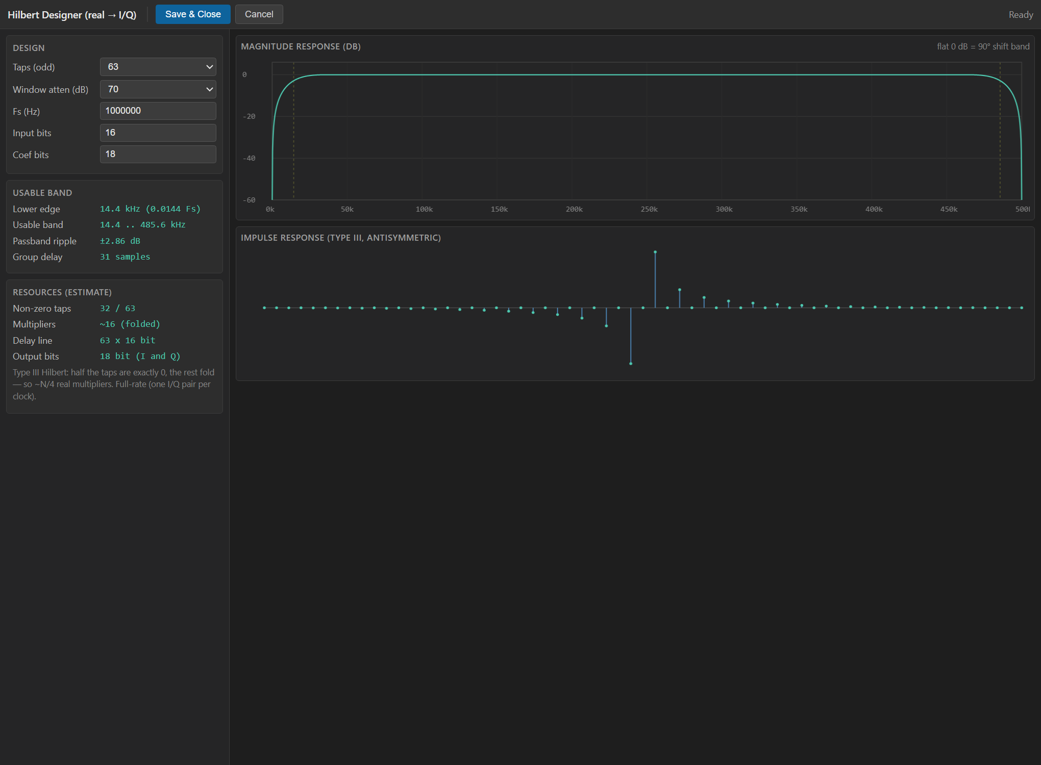
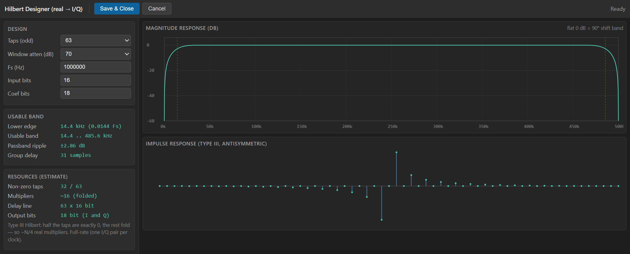
This block is configured from the Hilbert Designer, a custom WebView2
tool (not the standard property grid). Open it from the component to set the
tap count, Kaiser window attenuation, sample rate and bit widths, and watch
the design update live. The left panel edits Taps (odd), Window atten
(dB), Fs (Hz), Input bits and Coef bits; it reports the
resulting usable band (lower edge, bandwidth, passband ripple, group
delay) and a resource estimate (non-zero taps, multipliers after
folding, delay-line depth, output bits). The right panel plots the
magnitude response (flat 0 dB region = the 90-degree band) and the
antisymmetric impulse response. Save & Close writes a JSON config back
into the hidden HilbertProject property and mirrors the numeric fields
into the grid properties below.
Pin Description
(NumTaps-1)/2,
time-aligned to OUT_Q. Signed, InputSize + 2 bits.
Properties
Bit width of the real input sample (signed).
Bit width of the signed real input sample (also the reference full scale for coefficient normalisation). Range 4 to 32, default 16.Default: 16
Options: 4 5 6 7 8 9 10 11 12 13 14 15 16 17 18 19 20 21 22 23 24 25 26 27 28 29 30 31 32
Bit width of the Hilbert coefficients.
Bit width of each signed Hilbert coefficient. Larger values lower the stop-band / ripple floor at the cost of DSP width. One of 12, 14, 16, 18, 20, 24, default 18.Default: 18
Options: 12 14 16 18 20 24
Odd tap count (Type III). More taps = usable band closer to DC/Nyquist.
Odd tap count (Type III). More taps push the usable band closer to DC and Nyquist and sharpen the edges, at the cost of ~NumTaps/4
multipliers and (NumTaps-1)/2 samples of group delay. One of
15, 23, 31, 47, 63, 95, 127, 191, 255, default 63. An even value
is bumped up to the next odd number.
Default: 63
Options: 15 23 31 47 63 95 127 191 255
Kaiser window stopband attenuation: ripple/flatness of the passband.
Kaiser-window stop-band attenuation in dB; trades passband ripple / flatness against transition width. One of 40, 60, 70, 80, 100, default 70.Default: 70
Options: 40 60 70 80 100
Sample rate (for the designer’s frequency axis; does not change the hardware).
Sample rate in Hz. Used only for the designer’s frequency axis and the reported band edges; it does not change the synthesised hardware. Default 1000000.Default: 1000000
Config produced by the Hilbert Designer.
Hidden JSON blob produced by the Hilbert Designer (holds thehw
settings). Not user-editable in the grid; set it through the designer.
Usage
Mathematical model
For each sample the delay line holds the last NumTaps inputs (newest at
index 0). The Q channel is a direct-form FIR over the baked-in coefficients;
the I channel is simply the centre-tap of the delay line:
acc = sum_{i=0..NumTaps-1} dly[i] * COEFS[i]
OUT_Q[n] = acc >> COEF_SHIFT (COEF_SHIFT = CoefSize - 1)
OUT_I[n] = dly[MID_TAP] (MID_TAP = (NumTaps-1)/2)
Coefficient generation
The plugin computes the integer coefficients (HilbertCoefs) as follows:
beta = KaiserBeta(Atten)
w[k] = I0(beta * sqrt(1 - (2k/(N-1) - 1)^2)) / I0(beta) (Kaiser)
hw[k] = h[k-mid] * w[k] (h odd-m only)
The windowed response is normalised to unity magnitude at mid-band
(w = pi/2, i.e. Fs/4) and then quantised to a signed CoefSize-bit
integer with scale 2^(CoefSize-1); the post-MAC right shift COEF_SHIFT = CoefSize - 1 restores unity gain. Even taps (and the centre tap) come out
exactly zero and are pruned in synthesis.
Bit widths
Data is signed two’s complement.
IN: signedInputSizebits.OUT_I,OUT_Q: signedInputSize + 2bits (2 bits of output growth).- Internal accumulator:
InputSize + CoefSize + 8bits.
Group delay and band alignment
Group delay is (NumTaps - 1)/2 samples. If you split the analytic signal
back apart, delay any parallel real path by the same amount so it stays
aligned with I.
Latency and throughput
#pragma HLS PIPELINE II=1: one (I, Q) pair per input sample per clock.VALID_OUTis asserted high on every valid output sample.- All ports use the
ap_noneinterface (no ready/valid handshake).
Reset
RESET is the HLS synchronous reset (ap_rst); it clears the delay line.
Typical applications
- Real -> complex front end for the AM/FM demodulators, the mixer, or any complex-baseband RF block, without a quadrature LO.
- Single-sideband (SSB) generation / analysis.
- Envelope / instantaneous-phase extraction of a real band-pass signal.
Resources & Timing
-
Latency: 1 clock cycle (pipelined FIR; group delay = (NumTaps-1)/2 samples)
-
Throughput: 1 sample per clock (II=1)
Implemented with Vitis HLS. The Type III structure zeroes every even tap
and folds the antisymmetric pairs, so only about NumTaps/4 DSP48 slices
remain (the designer reports the exact multiplier count). Coefficients are
compile-time constants stored in hilbert_coefs.inc, so Vivado prunes the
zero taps automatically. The I path costs no multiplier: it is just a tap
of the shared delay line.