
Pulse Generator (PWM)
Generates a periodic digital pulse with programmable period and width. Can be used as a PWM modulator for duty cycle control.
Introduction
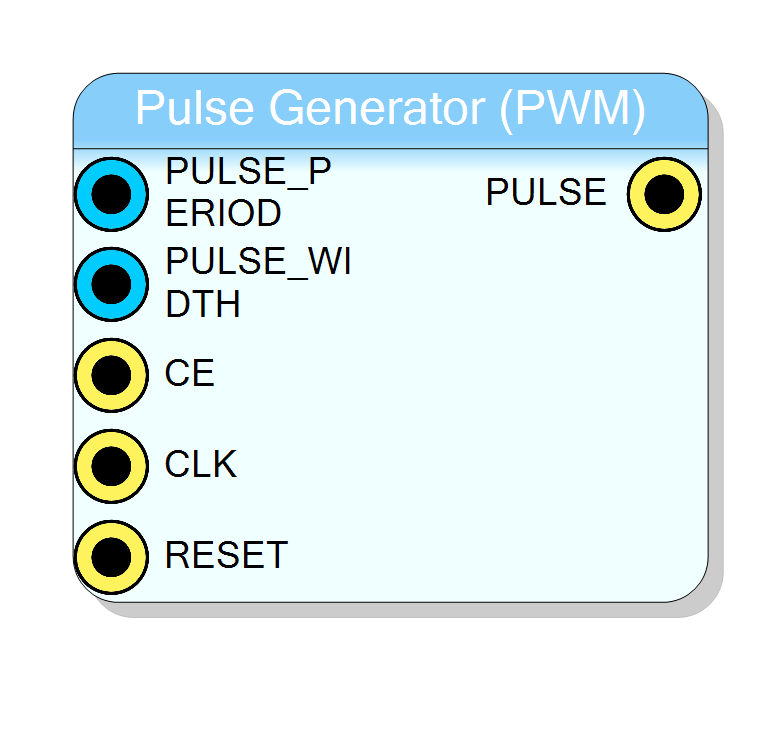
The Pulse Generator block generates a periodic digital pulse with programmable period and width. This block can be used as a PWM (Pulse Width Modulator) by dynamically changing the pulse width as a function of a numeric value.
Pin Description
Digital pulse output.
- HIGH (1): Counter < PULSE_WIDTH
- LOW (0): Counter >= PULSE_WIDTH
Usage
Operation
The pulse generator uses a simple counter-based architecture to produce periodic pulses:
- An internal 32-bit counter increments on each clock cycle (when CE is high)
- When the counter reaches PULSE_PERIOD - 1, it resets to zero
- The output is HIGH when the counter is less than PULSE_WIDTH, otherwise LOW
Timing Diagram
PULSE_PERIOD = 10, PULSE_WIDTH = 4
Counter: 0 1 2 3 4 5 6 7 8 9 0 1 2 3 ...
PULSE: ████████████____________████████████____
|<- WIDTH ->| |<- WIDTH ->|
|<-------- PERIOD ------->|
PWM Output Calculation
The duty cycle of the output signal is:
$$ \text{Duty Cycle} = \frac{\text{PULSE_WIDTH}}{\text{PULSE_PERIOD}} \times 100% $$
The output frequency is:
$$ f_{out} = \frac{f_{clk}}{\text{PULSE_PERIOD}} $$
where $f_{clk}$ is the frequency of the CLK input.
Example Calculations
For a 100 MHz clock:
| PULSE_PERIOD | PULSE_WIDTH | Output Frequency | Duty Cycle |
|---|---|---|---|
| 100 | 50 | 1 MHz | 50% |
| 1000 | 250 | 100 kHz | 25% |
| 10000 | 7500 | 10 kHz | 75% |
| 100000000 | 50000000 | 1 Hz | 50% |
PWM Applications
This block is commonly used for:
- LED brightness control: Vary duty cycle to change perceived brightness
- Motor speed control: PWM signal controls motor driver
- Audio generation: Simple square wave audio tones
- Timing pulses: Generate periodic trigger signals
- DAC emulation: Low-pass filtered PWM approximates analog voltage
Timing
| Parameter | Value |
|---|---|
| Latency | 0 clock cycles (combinatorial output) |
| Throughput | 1 sample per clock cycle |
The PULSE output changes on the same clock edge as the counter update, providing immediate response to period/width changes.
Important Notes
- PULSE_WIDTH must be less than PULSE_PERIOD for proper operation
- Setting PULSE_WIDTH = 0 produces a constant LOW output
- Setting PULSE_WIDTH >= PULSE_PERIOD produces a constant HIGH output
- Both PULSE_PERIOD and PULSE_WIDTH can be changed dynamically at runtime
Resources & Timing
-
Latency: 0 clock cycles
-
Throughput: 1 sample per clock cycle
Minimal resource usage: one 32-bit counter and comparators.