
Dual Oscilloscope
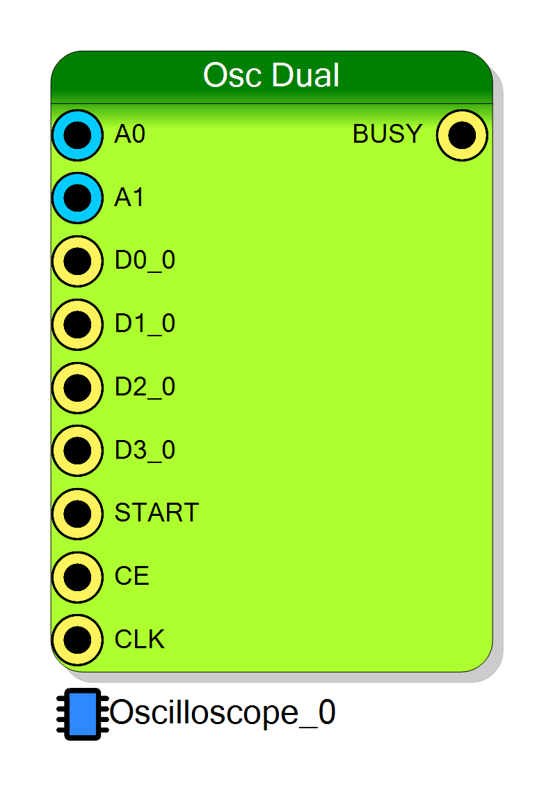
Oscilloscope Dual is a multi–channel oscilloscope IP core for Xilinx-7 devices able to acquire up to 32 analog input channels plus up to 4 groups of digital lines. The Dual architecture packs two analog samples per 32-bit RAM word. When digital inputs are enabled, each analog sample width is reduced to 14 bits so that a single 32-bit word carries: 14-bit channel A, 14-bit channel B, and 4 single-bit digital tracks (D0…D3). When digital inputs are disabled, each word carries two full 16-bit analog samples (channel pair). A programmable decimation factor (CONFIG_DECIMATOR) performs simple sub-sampling (rate reduction) without averaging.
Introduction
Principle of Operation
Let
- $f_s$ = input sampling frequency (raw sampling clock)
- $D = \text{CONFIG_DECIMATOR}$, $N = 2^D$ (decimation ratio)
- $x_k(i)$ = raw sample $k$ of analog channel i
- $y_m(i)$ = decimated output sample $m$ of channel i
When $D = 0$ there is no decimation and every raw sample is stored (subject
to circular buffer length).
When $D > 0$ the core keeps one raw sample every $N$ input cycles:
$$ y_m(i) = x_{mN}(i) $$
Dual Packing
The memory interface uses 32-bit words arranged as channel pairs:
-
Digital Disabled:
Word layout (bits 31:0):[15:0] = Channel (2n) [31:16] = Channel (2n+1)→ 2 × 16-bit samples.
-
Digital Enabled:
Each analog sample width becomes 14 bits to fit digital lines:[13:0] = Channel (2n) (A_low14) [27:14] = Channel (2n+1) (B_low14) [31:28] = D3 D2 D1 D0 (one bit each)(Total = 14 + 14 + 4 = 32 bits.)
Channels are logically labeled A0…A(N-1). The pairing is (A0,A1), (A2,A3), … in consecutive words.
Trigger Flow (Conceptual)
- ARM (
CONFIG_ARM0→1) arms the capture engine and clears internal counters. - Continuous Sampling writes into a circular buffer per channel pair.
- Trigger Evaluation each cycle (external START, analog threshold, software, or digital line).
- Trigger Latch stores the write pointer as trigger position (
READ_POSITION). - Post-Trigger Collection continues until total programmed samples (
Samples) are filled. - Ready:
READ_STATUS = 1, acquisition halts (buffer frozen for readout).
Deterministic behaviour is ensured because trigger evaluation, write pointer
updates and memory writes occur inside the same CLK_WRITE domain.
Pin Description
000).
CLK_WRITE).
Properties
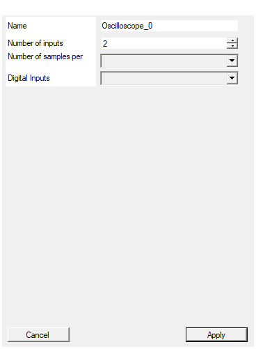
Set the name of the endpoint
Logical endpoint name used in register map; change if multiple oscilloscopes instantiated.Default: Oscilloscope_0
Set the number of input to the virtual block
Number of analog input channels (1 – 32). Must be even (channels handled in pairs).Default: 2
Range: 1 – 32
Set the number of samples stored for each acquisition
Circular buffer length per channel (power of two between 128 and 16384).Default: 1024
Options: 128 256 512 1024 2048 4096 8192 16384
Enable/Disable Digital Inputs
Enable/Disable 4 digital lines. When enabled, analog width shrinks to 14 bits to fit (14+14+4) packing.Default: Enabled
Options: Enabled Disabled
⚙️ Detailed Timing
Event Sequence
- ARM (
CONFIG_ARM0→1) clears counters & arms. - Sampling: every clock (period $T_{\text{CLK}} = 1/f_s$) one raw sample per channel is eligible.
- Decimation (if $D>0$): only samples where the free-running decimation counter = 0 are stored; others are skipped.
- Trigger Evaluation: performed each clock on instantaneous raw data.
- Trigger: when condition true → latch current buffer position.
- Completion: after post-trigger region filled → data ready.
Delay Between Trigger and Stored Sample
If trigger coincides with a stored (kept) sample (decimation counter = 0), that
sample is associated with the trigger.
If trigger occurs on a discarded raw sample (decimation counter ≠ 0), the last
stored sample before trigger represents the closest pre-trigger point. There is no averaging delay.
Latency pipeline (write path) = 2 clock cycles (register + RAM). Thus: $$ t_{\text{lat}} \approx 2T_{\text{CLK}} $$
Temporal distance between consecutive stored samples is: $$ \Delta t_{\text{stored}} = \begin{cases} T_{\text{CLK}} & D=0 \ N T_{\text{CLK}} & D>0 \end{cases} $$
Timing uncertainty (trigger to nearest stored sample) when $D>0$ is bounded by: $$ 0 \le \delta t < (N-1)T_{\text{CLK}} $$ because up to $N-1$ raw samples can be skipped after the last stored sample preceding the trigger.
Pre-Trigger Region
CONFIG_PRETRIGGER = P (in stored output samples). Required history in time:
$$ T_{\text{pre}} = \begin{cases} \dfrac{P}{f_s} & D=0 \ \dfrac{PN}{f_s} & D>0 \end{cases} $$
Full pre-trigger is only available if the system stayed armed long enough before the trigger.
Post-Trigger Region
With total stored samples $S = Samples$:
- Post-trigger samples = $S-P$
- Duration: $$ T_{\text{post}} = \begin{cases} \dfrac{S-P}{f_s} & D=0 \ \dfrac{(S-P)N}{f_s} & D>0 \end{cases} $$
Total span: $$ T_{\text{total}} = \begin{cases} \dfrac{S}{f_s} & D=0 \ \dfrac{SN}{f_s} & D>0 \end{cases} $$
Circular Buffer Reordering
After download, reorder so the trigger sample appears at index $P$:
- Read
READ_POSITION= $I_T$ (index of trigger-associated stored sample). - Compute: $$ \text{fix_position} = I_T - P $$
- If
fix_position > 0:Else:reordered = data[fix_position:] + data[:fix_position]idx = fix_position + S reordered = data[idx:] + data[:idx]
Word Decoding (Software)
Digital Disabled (16+16):
c
sampleA = word & 0xFFFF;
sampleB = (word >> 16) & 0xFFFF;
Digital Enabled (14+14+4):
c
sampleA = word & 0x3FFF; // bits 13:0
sampleB = (word >> 14) & 0x3FFF; // bits 27:14
d0 = (word >> 28) & 0x1;
d1 = (word >> 29) & 0x1;
d2 = (word >> 30) & 0x1;
d3 = (word >> 31) & 0x1;
Quick Reference
| Item | Formula / Meaning |
|---|---|
| Decimation ratio | $N = 2^D$ |
| Stored sample period | $T_{\text{CLK}}$ (D=0); $N T_{\text{CLK}}$ (D>0) |
| Pipeline latency (stored → readable) | $\approx 2T_{\text{CLK}}$ |
| Pre-trigger duration | $P/f_s$ (D=0); $(PN)/f_s$ (D>0) |
| Post-trigger duration | $(S-P)/f_s$ (D=0); $((S-P)N)/f_s$ (D>0) |
| Total duration | $S/f_s$ (D=0); $(SN)/f_s$ (D>0) |
| Trigger → nearest stored sample uncertainty (D>0) | $< (N-1)T_{\text{CLK}}$ |
| RAM word layout (digital off) | 2 × 16-bit analog |
| RAM word layout (digital on) | 14-bit A + 14-bit B + 4 digital bits |
Notes
- Choose $P$ considering available buffer depth; early triggers can reduce effective pre-trigger history.
- When digital is enabled, software must scale 14-bit values (e.g. left-shift by 2) if a uniform 16-bit range is expected downstream.
Oscilloscope Configuration Registers
CONFIG_ARM
Rising edge (0→1) arms acquisition (write 0 then 1 to re-arm).
CONFIG_DECIMATOR
Sets decimation exponent $D$ (0: no decimation; $N=2^D$). Implements sample skipping (no averaging).
CONFIG_TRIGGER_MODE
Trigger configuration (source, edge, software trigger bit, channel selection), same bit allocation as original oscilloscope core:
| Bits | Purpose | Description |
|---|---|---|
| 0–2 | Trigger Source | 000 external START; 001 analog; 010 software; 100–111 digital inputs 0–3 |
| 3 | Trigger Edge (analog only) | 0 rising, 1 falling |
| 6 | Software Trigger | Set 1 (with source = software) to trigger immediately |
| 8–15 | Channel Selection | Analog/digital channel index |
CONFIG_PRETRIGGER
Number $P$ of stored output samples to appear before the trigger after reordering.
CONFIG_TRIGGER_LEVEL
Threshold (LSB) for analog comparator when analog trigger enabled.
READ_STATUS
Acquisition status (0 = not ready, 1 = data ready).
READ_POSITION
Index $I_T$ (in raw stored sample space) of the trigger-associated stored sample.
Reading Waveform Data
When READ_STATUS = 1 read Samples * (channels/2) 32-bit words (each word holds two channel samples, plus optional digital bits). Reorder per above.