
RF FIR (programmable coefs)
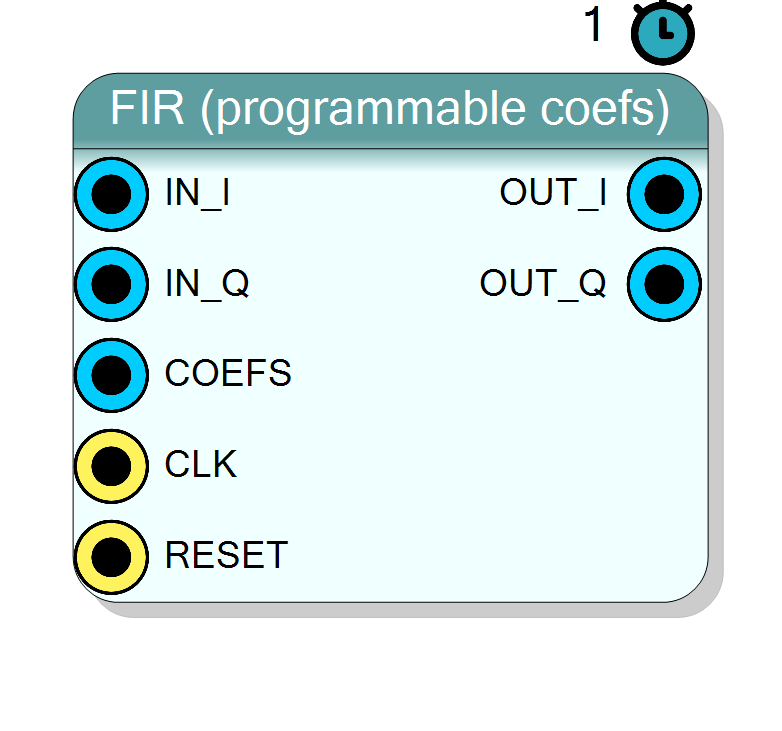
Direct-form FIR filter for a complex I/Q baseband stream. Same HLS core as the fixed-cutoff FIR, but the coefficient bus is exported as a top-level input pin (COEFS) so the coefficients can be updated at run time from the fabric.
Introduction
The FIR (programmable coefs) block is identical to
Component_FIR (low-pass fixed) except that the coefficient bus is
routed out as a top-level input pin. The user is responsible for driving
a valid packed coefficient vector on COEFS; the block never latches
it internally, so COEFS is an ap_stable bus and can be changed at
run time (typically from a register bank filled by the SDK).
IN_I ─┐
IN_Q ─┤ [ FIR ] ─── OUT_I / OUT_Q
COEFS ─┘
Pin Description
NumTaps * CoefSize bits wide.
Bit [(k+1)*CoefSize-1 : k*CoefSize] = signed h[k]. Bus is
ap_stable inside the HLS core: value is sampled combinationally
every clock, so it can be updated at run time from the fabric.
Properties
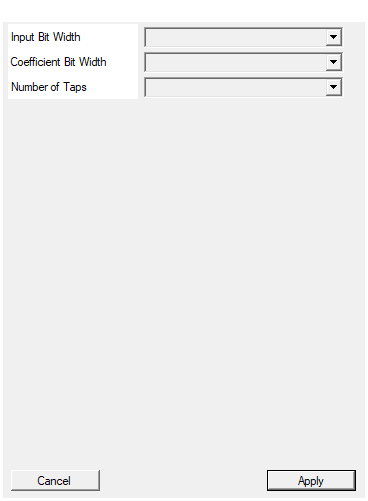
Bit width of each I and Q input sample (signed)
Bit width of each I / Q input sample. Range 4 to 32, default 16.Default: 16
Options: 4 5 6 7 8 9 10 11 12 13 14 15 16 17 18 19 20 21 22 23 24 25 26 27 28 29 30 31 32
Bit width of each coefficient (signed). Determines the width of the COEFS bus (NumTaps * CoefSize).
Bit width of each signed coefficient. Sets the width of theCOEFS bus together with NumTaps. Default 16.
Default: 16
Options: 8 10 12 14 16 18 20 24
Number of filter taps (filter order = NumTaps - 1). Determines the width of the COEFS bus (NumTaps * CoefSize).
Number of filter taps (filter order =NumTaps - 1). Sets the
width of the COEFS bus together with CoefSize. Default 32.
Default: 32
Options: 8 16 24 32 48 64 96 128
Usage
COEFS bus layout
The bus is packed little-endian per tap: bit slice
[(k+1)*CoefSize-1 : k*CoefSize] of COEFS holds the signed
coefficient h[k], i.e. h[0] is at the LSBs of the bus.
COEFS bit index: packedSize-1 ... CoefSize CoefSize-1 ... 0
+----------+---+------------+---------+ ... +---+
| h[N-1] |...| h[1] | h[0] |
+----------+---+------------+--------------------+
where packedSize = NumTaps * CoefSize. Each h[k] is signed two’s
complement, CoefSize bits.
Data path
Same as Component_FIR:
y_c[n] = sum_{k=0..NumTaps-1} h[k] * x_c[n-k] for c in {I,Q}
Same output width InputSize + CoefSize + 8, same II=1 pipeline, same
1-clock latency.
Coefficient design (host side)
The coefficients are the responsibility of the driver / firmware. The
easiest recipe for a real low-pass is windowed sinc, DC-normalised and
quantised to signed CoefSize bits with a scale of 2^(CoefSize-1)-1
(identical to what Component_FIR does internally). The Python
testbench tb/fir/fir_tb.py contains a reference implementation of
the coefficient generator that you can copy verbatim.
Typical applications
- Software-defined channel-select filter: change bandwidth without resynthesising the bitstream.
- Matched filter whose shape depends on the sample rate at run time.
- Adaptive equaliser where a small state machine outside the block updates the coefficients.
Resources & Timing
-
Latency: 1 clock cycle
-
Throughput: 1 sample per clock (II=1)
Implemented with Vitis HLS. NumTaps DSP48 slices per channel. Because
the coefficients are ap_stable (not compile-time constant) Vivado
cannot optimise them away, so DSP usage is deterministic.