
Not Equal [TM]
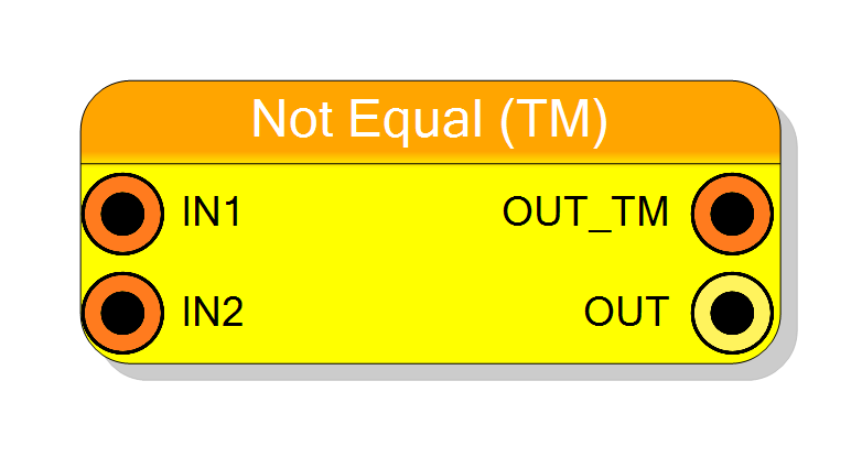
Time-multiplexed inequality comparator. Processes multiple not-equal comparisons in parallel on TM data streams. Supports TM factors 2-32 with optional mixed input modes.
Introduction
This block performs parallel inequality comparisons on time-multiplexed data streams. Each TM phase is compared independently. See the non-TM Not Equal component for detailed comparison operation description.
Pin Description
Properties
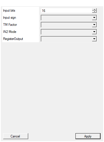
Set the number of bits of the input (per TM phase)
Bits per sample (per TM phase). Range: 2-2048.Default: 16
Range: 2 – 2048
Select the sign/unsign of the input
UNSIGNED or SIGNED interpretation.Default: UNSIGNED
Options: UNSIGNED SIGNED
Select the TM Factor of the input
Time-multiplexing factor: 2, 4, 8, 16, or 32.Default: 4
Options: 2 4 8 16 32
Select if IN2 is Time-Multiplexed or a single STD signal
TM (phase-matched) or STD (broadcast to all phases).Default: TM
Options: TM STD
Enable one pipeline stage adding a register
Disable (zero latency) or Enable (1 cycle latency).Default: Disable
Options: Disable Enable
Functional description
Replicates the Not Equal comparator N times (where N = TM Factor) for parallel operation. Supports both TM-to-TM and TM-to-STD comparison modes via the IN2 Mode property.
Latency
| RegisterOutput | Latency (clock cycles) |
|---|---|
| Disable | 0 |
| Enable | 1 |