
Constant Time
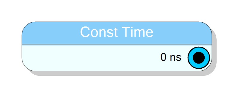
Generates a constant time value converted to clock cycles based on system frequency. Supports nanosecond (ns), microsecond (us), millisecond (ms), and second (s) units. Automatically scales time to FPGA clock cycles for use in timers, delays, and timeout logic. Zero latency.
Introduction
This block generates a constant time value represented as a number of clock cycles. The user specifies a time duration in human-readable units (ns, µs, ms, s), and the component automatically converts it to clock cycles based on the configured system clock frequency.
This simplifies timer and delay logic by abstracting clock cycle calculations:
$$ \mathrm{Clock\ Cycles} = \text{Time} \times \text{Clock\ Frequency} $$
The output is a bit-vector constant representing the integer number of clock cycles, suitable for direct use in counters, timers, and timeout logic.
Pin Description
Constant time value represented as clock cycles, always combinational (zero latency). Width: Configurable via N Bits property (16, 24, 32, 48, 56, or 64 bits).
The output is an unsigned integer representing the number of clock cycles equivalent to the specified time duration at the configured clock frequency. Suitable for direct use in counters, comparators, or timeout logic.
Properties
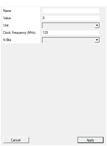
Set the value of the constant. Can be left blank
Optional custom label for the component. If specified, replaces the default title “Const Time” on the schematic symbol. Leave blank to use default.Set the value of the constant.
Time duration value in the selected unit. Supports decimal notation (e.g., 1.5, 100, 0.001). Use comma or period as decimal separator. Combined with Unit to define the total time.Default: 0
Set time unit
Time unit for the Value property. Choose from: “ns” (nanoseconds), “us” (microseconds), “ms” (milliseconds), or “s” (seconds). The component scales the value accordingly.Default: ns
Options: ns us ms s
Set clock frequency in MHz.
FPGA system clock frequency in MHz. Used to convert time to clock cycles. Example: 125 for 125 MHz. Must match the clock domain where this constant is used. Higher frequencies provide better time resolution.Default: 125
Set number of bits
Output bit width (N Bits). Choose from: 16, 24, 32, 48, 56, or 64 bits. Select sufficient width to represent the maximum clock cycle count. Smaller widths save resources but limit maximum representable time.Default: 32
Options: 16 24 32 48 56 64
Functional description
The component implements a time-to-clock-cycle converter for constant time values. Given a time $T$, time unit, and clock frequency $f_{\text{clk}}$, the output is:
$$ \mathrm{CONST} = \lfloor T \times f_{\text{clk}} \rceil $$
where:
- $T$ = time value in selected units (ns, µs, ms, s)
- $f_{\text{clk}}$ = clock frequency in Hz
- $\lfloor \cdot \rceil$ = rounding to nearest integer
Time unit conversion
The component supports four time units:
| Unit | Symbol | Scale Factor | Example |
|---|---|---|---|
| Nanoseconds | ns | $10^{-9}$ s | 100 ns = 0.0000001 s |
| Microseconds | µs | $10^{-6}$ s | 50 µs = 0.00005 s |
| Milliseconds | ms | $10^{-3}$ s | 10 ms = 0.01 s |
| Seconds | s | $1$ s | 2 s = 2.0 s |
Clock cycle calculation
The conversion formula depends on the clock frequency (specified in MHz):
$$ \text{Cycles} = \text{round}\left(T_{\text{seconds}} \times f_{\text{MHz}} \times 10^6\right) $$
Example: 100 µs @ 125 MHz
- Convert to seconds: $100 \times 10^{-6} = 0.0001$ s
- Multiply by frequency: $0.0001 \times 125 \times 10^6 = 12500$ cycles
- Result:
0x30D4(16-bit representation)
Bit width selection
The N Bits property determines the output width. Choose sufficient bits to represent the maximum clock cycle count:
Required bits for time $T$ (seconds) at frequency $f$ (MHz): $$ \text{Bits needed} = \lceil \log_2(T \times f \times 10^6) \rceil $$
Common configurations:
| N Bits | Maximum Cycles | Example (@ 100 MHz) |
|---|---|---|
| 16 | 65,535 | 655 µs |
| 24 | 16,777,215 | 167 ms |
| 32 | 4,294,967,295 | 42.9 seconds |
| 48 | 281,474,976,710,656 | ~3,257 days |
| 64 | 2^64 - 1 | ~5.8 million years |
Practical examples
Example 1: 1 ms timeout @ 125 MHz
Value: 1
Unit: ms
Clock Frequency: 125 MHz
N Bits: 32
Calculation:
Cycles = 1e-3 × 125e6 = 125,000 = 0x1E848
Output: 32-bit constant = 0x0001E848
Example 2: 100 ns delay @ 200 MHz
Value: 100
Unit: ns
Clock Frequency: 200 MHz
N Bits: 16
Calculation:
Cycles = 100e-9 × 200e6 = 20 = 0x14
Output: 16-bit constant = 0x0014
Example 3: 5 second timer @ 50 MHz
Value: 5
Unit: s
Clock Frequency: 50 MHz
N Bits: 32
Calculation:
Cycles = 5 × 50e6 = 250,000,000 = 0xEE6B280
Output: 32-bit constant = 0x0EE6B280
Overflow handling
If the calculated cycle count exceeds the maximum value for N Bits, the result is clamped to the maximum representable value:
$$ \text{Output} = \min(\text{Calculated Cycles}, 2^{\text{N Bits}} - 1) $$
Choose a larger bit width to avoid clamping.
Implementation details
The VHDL implementation generates a hexadecimal constant:
vhdl
signal CONST : STD_LOGIC_VECTOR(N_Bits-1 downto 0);
CONST <= x"<hex_value>";
The conversion from time to clock cycles happens at compile time, so there is no runtime overhead.
Timing
The component is purely combinational with zero latency:
| Property | Latency (clock cycles) |
|---|---|
| Constant Time | 0 |
The output is available immediately after FPGA configuration.
Typical use cases
- Timeout timers: Define maximum wait times for communication protocols or watchdogs
- Delay generators: Create precise delays for sequencing or synchronization
- Pulse width modulators: Set duty cycle or period values in clock cycles
- Baud rate generators: Calculate divisor values for UART or serial interfaces
- Sampling intervals: Define fixed sampling periods for ADC or DAC systems
- Debounce timers: Set debounce durations for mechanical switches (typically 10-50 ms)
- Control loop periods: Define fixed update rates for PID or state machine loops
Design recommendations
Choosing clock frequency
Set Clock Frequency to match your FPGA’s system clock. For multi-clock designs, use the frequency of the domain where the constant will be used.
Choosing bit width
- 16 bits: Sufficient for short delays (<1 ms @ 100 MHz)
- 24 bits: Good for medium delays (up to ~167 ms @ 100 MHz)
- 32 bits: Recommended for general-purpose timers (seconds range)
- 48/64 bits: Only needed for extremely long timeouts (minutes to hours)
Precision considerations
The conversion rounds to the nearest integer cycle, so the actual time may differ slightly from the specified value:
$$ \text{Actual Time} = \frac{\text{Rounded Cycles}}{f_{\text{clk}}} $$
For high-precision timing, verify that the rounding error is acceptable.