
Pattern Generator
Generates arbitrary digital patterns from a ROM loaded with user-defined data. Supports configurable bit width, memory size, and multiple data formats.
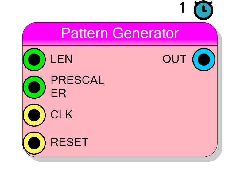
Introduction
The Pattern Generator block produces digital output signals based on data loaded from a user-defined file. The ROM content is read sequentially and output at a configurable rate, making it suitable for generating arbitrary waveforms, test patterns, or stimulus signals.
The data file can be loaded directly through the Rom Content property, which opens a file dialog to select a text file containing the pattern data.
Pin Description
Clock divider value (integer). Output rate = CLK / (PRESCALER + 1).
- 0: Output at full clock rate
- N: Output every N+1 clock cycles Default: 0.
Properties
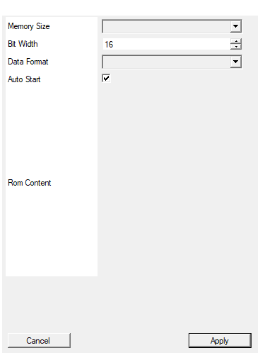
Set the amount of memory in number of words
Number of words in the ROM. Available values: 4, 8, 16, 32, 64, 128, 256, 512, 1024, 2048, 4096, 8192, 16384, 32756, 65536, default 1024.Default: 1024
Options: 4 8 16 32 64 128 256 512 1024 2048 4096 8192 16384 32756 65536
Set the size in bits of the data
Size of each data word in bits. Range: 1 to 1024, default 16.Default: 16
Range: 1 – 1024
Select data format as Decimal or Hexadecimal
Data format for interpreting the input file.
- HEX: Hexadecimal numbers without 0x prefix
- SIGNED DECIMAL: Signed decimal integers
- DECIMAL: Unsigned decimal integers Default: HEX.
Default: HEX
Options: HEX SIGNED DECIMAL DECIMAL
Check this option to configure the pattern generator to automatic start the generation and loop forever
Enable automatic start and continuous looping. When enabled, the START pin is hidden and generation loops forever. Default: True.Default: True
Usage
Operation
The Pattern Generator reads data from an internal ROM and outputs it sequentially:
- On each clock cycle (divided by PRESCALER), the next ROM address is read
- The data at that address is output on the OUT port
- When LEN samples have been output, generation stops (or loops if Auto Start is enabled)
Data File Format
The Rom Content property allows loading a text file containing the pattern data. The file format depends on the Data Format property setting:
HEX Format
Each line contains a hexadecimal number without the 0x prefix:
A012
12
133
F0F1
FFFF
0000
SIGNED DECIMAL Format
Each line contains a signed decimal integer:
-32768
-100
0
100
32767
DECIMAL (Unsigned) Format
Each line contains an unsigned decimal integer:
0
100
255
1000
65535
File Parsing Rules
When loading a file, the following separators are automatically converted to newlines:
- Comma (
,) - Semicolon (
;) - Space (
- Tab
This allows flexible input formats like CSV files:
A012, 12, 133, F0F1
is equivalent to:
A012
12
133
F0F1
Memory Configuration
| Property | Description |
|---|---|
| Memory Size | Number of words in ROM (4 to 65536) |
| Bit Width | Size of each word in bits (1 to 1024) |
Important: If the data file contains fewer lines than Memory Size, the remaining addresses are filled with zeros.
Data Format Property
The Data Format property determines how numbers in the file are interpreted:
| Format | Description | Example Values |
|---|---|---|
| HEX | Hexadecimal without 0x prefix | FF, A012, 1234 |
| SIGNED DECIMAL | Signed integer | -128, 0, 127 |
| DECIMAL | Unsigned integer | 0, 128, 255 |
Note for Xilinx FPGAs: The internal .mem file always uses hexadecimal format. If SIGNED DECIMAL or DECIMAL is selected, values are automatically converted to hexadecimal during compilation.
Output Timing
The output sample rate is controlled by the PRESCALER input:
$$ f_{out} = \frac{f_{clk}}{\text{PRESCALER} + 1} $$
where $f_{clk}$ is the frequency of the CLK input.
| PRESCALER | Clock Division | Output Rate @ 100 MHz |
|---|---|---|
| 0 | 1 | 100 MHz |
| 1 | 2 | 50 MHz |
| 9 | 10 | 10 MHz |
| 99 | 100 | 1 MHz |
Auto Start Mode
When Auto Start is enabled:
- Generation starts automatically after reset
- Pattern loops continuously
- The START pin is not shown on the symbol
When Auto Start is disabled:
- The START pin appears on the symbol
- Generation begins on rising edge of START
- Pattern plays once per START pulse
Timing
| Parameter | Value |
|---|---|
| Latency | 1 clock cycle |
| Throughput | 1 sample per (PRESCALER+1) clock cycles |
Resources & Timing
-
Latency: 1 clock cycle
-
Throughput: 1 sample per (PRESCALER+1) clock cycles
Uses Block RAM for ROM storage. Memory usage depends on Memory Size and Bit Width settings.