
RF Halfband Decimator (prog)
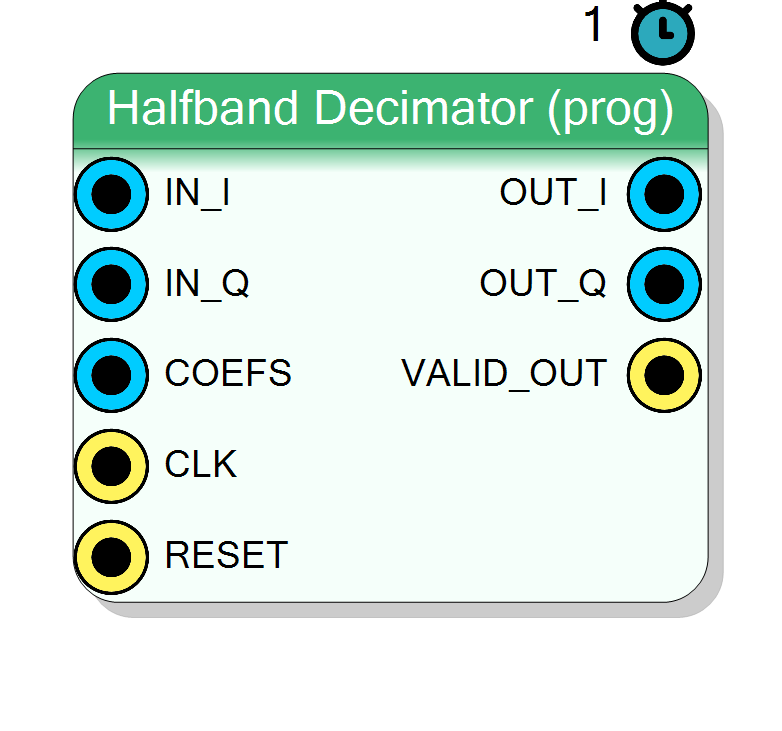
Complex I/Q halfband FIR decimator (fixed 2:1 rate change) whose coefficient set is driven at run time through a top-level COEFS bus instead of being baked into the netlist. Same datapath and decimation behaviour as the fixed variant, with reloadable taps.
Introduction
The Halfband Decimator (prog) block is the run-time programmable
sibling of halfband_decim. It filters a complex baseband stream and
decimates by exactly two, but its NumTaps coefficients are supplied
live on a top-level COEFS pin rather than computed by the plugin and
frozen into the VHDL.
A halfband FIR is a low-pass with its cutoff at Fs/4; at that frequency every second impulse-response tap is zero (except the centre) and the response is symmetric, so a halfband is the cheapest FIR for a 2:1 decimation. See halfband_decim for the full theory.
IN_I ─┐ ┌── OUT_I (rate = IN rate / 2)
IN_Q ─┤ [ halfband ] ├── OUT_Q
COEFS ─┘ h[k] live └── VALID_OUT
What “programmable” means here
In the fixed variant the plugin runs ComputeHalfbandCoefs(), packs the
quantised taps into a constant and wires that constant to the internal
coefs_packed port. In this prog variant that same port is instead
exposed as a top-level input pin COEFS (NumTaps * CoefSize bits,
packed little-tap-first). You drive it from fabric — a register file, a
BRAM, an AXI-lite mapped word, a DMA, or another block — and can change
the filter response at run time without re-synthesising.
You are responsible for computing the halfband taps yourself: quantise a
unity-DC-gain, Fs/4-cutoff low-pass to signed CoefSize-bit words and
concatenate them so that
COEFS[(k+1)*CoefSize-1 : k*CoefSize] = signed h[k], for
k = 0 .. NumTaps-1.
Pin Description
k lives in
bits [(k+1)*CoefSize-1 : k*CoefSize] as a signed CoefSize-bit value.
Treated as slowly-varying (ap_stable); drive it from a register file,
BRAM or DMA. Supply Fs/4-cutoff, unity-DC-gain halfband taps.
Properties
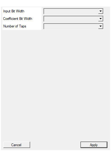
Bit width of each I/Q input sample (signed).
Bit width of each signed I / Q input sample. Range 4 to 32, default 16. Changing it triggers a redesign.Default: 16
Options: 4 5 6 7 8 9 10 11 12 13 14 15 16 17 18 19 20 21 22 23 24 25 26 27 28 29 30 31 32
Bit width of each coefficient (signed). Sets the COEFS bus width together with NumTaps.
Bit width of each signed coefficient. Choices 10, 12, 14, 16, 18, 20, 24; default 16. Sets the COEFS bus width together with NumTaps. Changing it triggers a redesign (COEFS width changes).Default: 16
Options: 10 12 14 16 18 20 24
Number of taps. Sets the COEFS bus width together with CoefSize.
Number of filter taps (filter order =NumTaps - 1). Choices
7, 11, 15, 19, 23, 27, 31, 39, 47, 63; default 15. Sets the
COEFS bus width together with CoefSize. Changing it triggers a
redesign. Use a canonical halfband length of the form 4k+3.
Default: 15
Options: 7 11 15 19 23 27 31 39 47 63
Usage
Coefficient bus (COEFS)
COEFS is a single wide std_logic_vector of width NumTaps * CoefSize.
Tap k occupies bit range [(k+1)*CoefSize-1 : k*CoefSize] and is a
signed two’s-complement CoefSize-bit value. Inside the HLS core the bus
carries an ap_stable attribute: it is sampled every clock and treated as
slowly varying, so update it only when the datapath is quiescent (or
accept a transient during the reload) to avoid a partially-updated tap set.
Because the taps are unknown at synthesis time, Vivado cannot prune
the zero taps: the programmable variant instantiates the full NumTaps
multipliers per channel. If you never need to change the response, prefer
the fixed variant for the DSP saving.
Mathematical model
For each channel c in {I, Q}, at every input sample n
acc_c[n] = sum_{k=0..NumTaps-1} h[k] * x_c[n-k]
and the block keeps one result out of two: y_c[m] = acc_c[2m].
Bit widths
Data is treated as signed two’s complement.
IN_I,IN_Q: signedInputSizebits.COEFS:NumTaps * CoefSizebits (packed signed taps).- internal product :
InputSize + CoefSizebits. OUT_I,OUT_Q: signedInputSize + CoefSize + 8bits.
The extra 8 accumulator bits (ACC_GROWTH = 8) prevent overflow of the
tap sum up to 256 taps.
VALID_OUT / strobe behaviour
Identical to the fixed variant. The core runs at the input rate
(II=1, a new pair every clock) and asserts VALID_OUT on every other
clock to flag the decimated output samples; the output rate is therefore
input rate / 2. The internal keep phase starts true after reset, so
the first post-reset output is valid. Gate downstream logic on
VALID_OUT.
Latency and reset
#pragma HLS PIPELINE II=1: one input pair per clock.- 1-clock reported latency.
- Data ports use
ap_none;COEFSusesap_stable. RESET(ap_rst) clears the delay lines and re-arms the decimation phase. It does not clearCOEFS, which is driven externally.
Typical applications
- DDC 2:1 stages where the passband must be re-tuned at run time (e.g. switchable channel bandwidths).
- Adaptive / calibrated filters whose taps are loaded from software.
- Sharing one bitstream across products that need different responses.
Resources & Timing
-
Latency: 1 clock cycle (reported)
-
Throughput: Accepts 1 input pair per clock (II=1); emits 1 valid output pair every 2 input clocks (output rate = input rate / 2).
Implemented with Vitis HLS. Because the coefficients arrive at run time on COEFS, Vivado cannot prune zero taps: the full NumTaps multipliers per channel are instantiated (more DSPs than the fixed variant). COEFS is ap_stable — update it only when the pipeline is idle or tolerate a brief transient. Fixed 2:1 rate change is built into the block.