
Veto
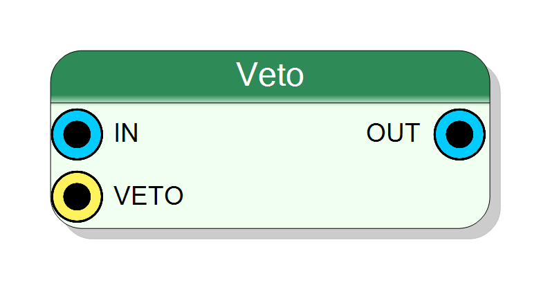
Conditional signal blocking (VETO logic). When the VETO input is active (1), the output is forced to 0 regardless of the IN signal. When VETO is inactive (0), the output equals the input. Used for masking or blocking signals. Pure combinational logic (zero latency).
Introduction
This block implements VETO logic, a conditional gating mechanism for signals. The component has two inputs: a data input (IN) and a control input (VETO).
Operation:
- When VETO = 1 (active): OUT is forced to 0, blocking the input signal
- When VETO = 0 (inactive): OUT = IN, signal passes through unmodified
The operation is purely combinational with zero clock latency:
$$ \mathrm{OUT} = \mathrm{IN} \land \neg\mathrm{VETO}, $$
where $\land$ is AND and $\neg$ is NOT. The VETO input effectively masks or blocks the data signal when active.
Pin Description
Control input (1 bit wide, extended to match IN width).
- VETO = 1: Output is forced to all zeros (signal blocked)
- VETO = 0: Output equals IN (signal passes through) Single-bit input that controls the entire output width.
Properties
Functional description
The component implements VETO logic (also called conditional masking or gating) in VHDL. It combines the input signal with the inverted VETO control:
$$ y = x \land \neg v, $$
where:
- $x$ → IN (data input)
- $v$ → VETO (control input)
- $y$ → OUT (output)
- $\land$ → logical AND
- $\neg$ → logical NOT
Truth table for single-bit operation:
| IN | VETO | OUT |
|---|---|---|
| 0 | 0 | 0 |
| 0 | 1 | 0 |
| 1 | 0 | 1 |
| 1 | 1 | 0 |
For multi-bit inputs, the VETO signal (single bit) is extended to match the width of the IN signal, and the operation is applied to all bits simultaneously.
Example
Given an 8-bit IN signal and 1-bit VETO:
- IN =
10110011, VETO =0→ OUT =10110011(signal passes through) - IN =
10110011, VETO =1→ OUT =00000000(signal blocked)
Mathematical background
The VETO operation is equivalent to an AND gate with inverted control signal. It is commonly used in:
- Signal masking: Blocking unwanted signals based on a condition
- Event gating: Allowing events only when a control signal permits
- Safety interlocks: Disabling outputs during unsafe conditions
- Trigger logic: Vetoing triggers during busy or dead time periods
Timing
The component is purely combinational with zero latency:
| Property | Latency (clock cycles) |
|---|---|
| Veto | 0 |
The output changes immediately (after propagation delay) when either input changes.
Typical use cases
- Event veto in data acquisition systems
- Trigger blocking during busy periods
- Signal masking in detector readout
- Safety interlock logic
- Conditional signal gating in control systems